


ひずみ
ひずみゲージは、より良い、より安全な製品を作るために、疲労を測定し、材料を試験するための重要な資産です。構造(Structural )耐久性試験、構造健全性モニタリング、OEMトランスデューサの製造のいずれにおいても、HBKの光学式および電気式ひずみゲージは第一の選択肢です。
続きを読み取る
ホイートストンブリッジは、電気抵抗の測定に様々な方法で使用することができます。
後者の方法は、ひずみゲージの技術に関して使用されます。これにより、通常10-4~10-2Ω/Ωのオーダーであるひずみゲージの抵抗値の相対変化を高精度に測定することができます。
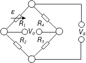
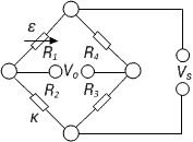
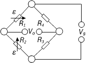
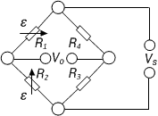
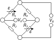
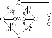
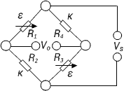
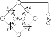
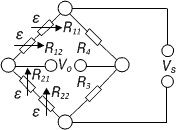
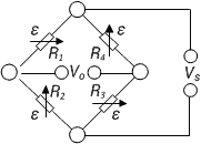
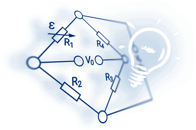
下の画像は、電気的に同じホイートストンブリッジの2種類の図です。図aはホイートストンが使用される通常のひし形表現、図bは同じ回路の表現ですが、電気に詳しくない人の方が分かりやすいでしょう。
ブリッジ回路の4つのアーム(分岐)は抵抗R1~R4で形成されています。ブリッジのコーナーポイント2および3は,ブリッジの励磁電圧Vs.の接続を指定します。ブリッジ出力電圧V0(測定信号)は、コーナーポイント1とコーナーポイント4で得られます。
注)ブリッジの構成部品や接続の指定に一般的な決まりはありません。既存の文献には様々な表記があり,それがブリッジの式に反映されています.したがって,式に使用される呼称や指標は,ブリッジネットワークにおける位置づけを考慮し,誤解のないようにすることが肝要である。
ブリッジの励磁は通常、印加、安定化された直流電圧、または交流電圧Vsである。供給電圧Vsがブリッジ供給点2、3に印加されると、供給電圧はブリッジの2つの半部R1、R2およびR4、R3において、対応するブリッジ抵抗の比として分割され、すなわちブリッジの各半部は分圧器を形成する。
R1、R2およびR3、R4上の電気抵抗からの電圧の差により、ブリッジはアンバランスになり得ます。これは次のように計算することができます。
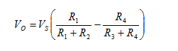
もしブリッジのバランスがとれているならば、
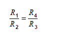
ここで、ブリッジ出力電圧V0はゼロです。
予め設定されたひずみで、ひずみゲージの抵抗値はΔRだけ変化します。このことから、次の式が得られます。
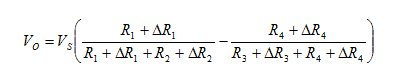
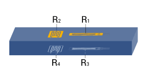
ひずみ測定の場合、ホイートストンブリッジの抵抗R1とR2は等しくなければなりません。R3、R4についても同様です。
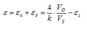
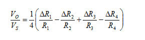
いくつかの仮定と単純化により、以下の式が求められます(さらなる説明は、HBK の書籍「An Introduction to Measurements using Strain Gauges」に記載されています)。
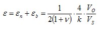
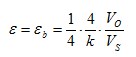
計算の最後のステップでは、ΔR/Rの項を次のように置き換える必要があります。
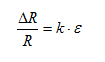
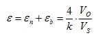
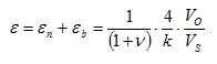
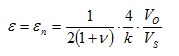
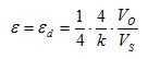
こで、kはひずみゲージのkファクター、εはひずみです。これにより、次のようになる。
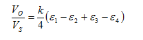
この式は、ブリッジ内のすべての抵抗が変化することを前提としています。例えば、変換器や同様の機能を持つ試験体ではこのような状況が発生します。実験的なテストでは、このようなことはほとんどなく、通常はブリッジアームの一部にのみアクティブなひずみゲージがあり、残りはブリッジ補完抵抗で構成されています。1/4ブリッジ、ハーフブリッジ、ダブルクォーターブリッジまたはダイアゴナルブリッジ、フルブリッジなど、さまざまな形式の呼称が一般的です。

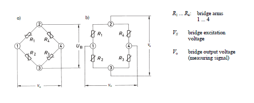
Get a complete overview of the topic of "An Introduction to Measurements using Strain Gauges" - in Karl Hofmann's #1 reference book on stress analysis using strain gauges. In this 250-page, richly illustrated book, Karl Hoffmann describes, in plain language, the fundamentals of strain gauge measurement, ranging from gauge selection through analysis and evaluation of acquired data. Take a look at the book!
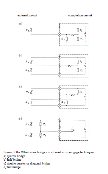
測定対象に応じて、測定箇所に1個または複数個のひずみゲージを使用します。このような配置を示すために、フルブリッジ、ハーフブリッジ、クォーターブリッジなどの呼称が使われますが、実はこれらは正しくありません。実際には、測定に使用される回路は常に完全であり、ひずみゲージと試験片によって完全または部分的に形成されます。そして、機器に内蔵されている固定抵抗器によって完成します。
一般的に変換器は、実験的なテストに関連する測定よりも厳しい精度要件に準拠する必要があります。したがって、変換器は常に4つのアームすべてにアクティブなひずみゲージを持つフルブリッジ回路を備えている必要があります。
異なる種類の干渉を排除する必要がある場合は、フルブリッジまたはハーフブリッジ回路を応力解析に使用する必要があります。重要な条件は、圧縮応力や引張応力、曲げ、せん断、ねじり力など、異なる応力のケースが明確に区別されることです。
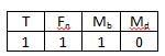
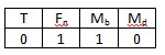
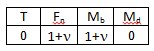
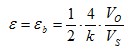
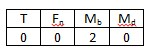
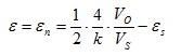
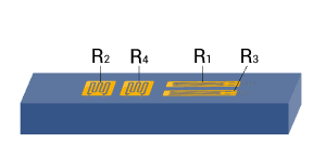
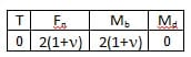
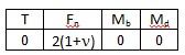
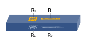
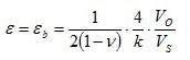
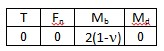
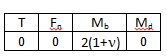
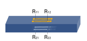
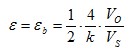
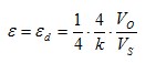
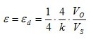
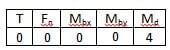
下の表は、法線力、曲げモーメント、トルク、温度に対する、ひずみゲージの幾何学的位置、使用するブリッジ回路のタイプ、結果として得られるブリッジ係数Bの依存性を示しています。各例で示されている小さな表は、影響を与える量の種類ごとにブリッジファクターBを指定しています。この方程式はブリッジ出力信号VO/VSから有効ひずみを計算するために使用されます。
|
Bridge configuration |
External impacts measured: |
Application |
Description |
Advantages and disadvantages |
||
| 1 |
|
|
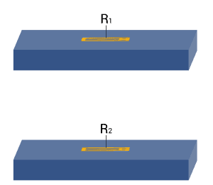
| Strain measurement on a tension/ compression bar Strain measurement on a bending beam | Simple quarter bridge
Simple quarter bridge circuit with one active strain gauge | + Easy installation - Normal and bending strain are superimposed - Temperature effects not automatically compensated |
| 2 |
|
|
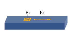
| Strain measurement on a tension/ compression bar Strain measurement on a bending beam | Quarter bridge with an external dummy strain gauge
Two quarter bridge circuits, one actively measures strain, the other is mounted on a passive component made of the same material, which is not strained | + Temperature effects are well compensated - Normal and bending strain cannot be separated (superimposed bending) |
| 3 |
|
|
| Strain measurement on a tension/ compression bar Strain measurement on a bending beam | Poisson half-bridge
Two active strain gauges connected as a half bridge, one of them positioned at 90° to the other | + Temperature effects are well compensated when material is isotrop |
| 4 |
|
|
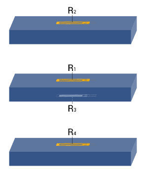
| Strain measurement on a bending beam | Half bridge
Two strain gauges are installed on opposite sides of the structure | + Temperature effects are well compensated + Separation of normal and bending strain (only the bending effect is measured) |
| 5 |
|
|
| Strain measurement on a tension/ compression bar | Diagonal bridge
Two strain gauges are installed on opposite sides of the structure | + Normal strain is measured independently of bending strain (bending is excluded) |
| 6 |
|
|
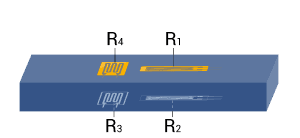
| Strain measurement on a tension/ compression bar Strain measurement on a bending beam | Full bridge
4 strain gauges are installed on one side of the structure as a full bridge | + Temperature effects are well compensated + High output signal and excellent common mode rejection (CMR) - Normal and bending strain cannot be separated (superimposed bending) |
| 7 |
|
|
| Strain measurement on a tension/ compression bar | Diagonal bridge with dummy gauges
Two active strain gauges, two passive strain gauges | + Normal strain is measured independently of bending strain (bending is excluded) + Temperature effects are well compensated |
| 8 |
|
|
| Strain measurement on a bending beam | Full bridge
Four active strain gauges are connected as a full bridge | + Separation of normal and bending strain (only the bending effect is measured) + High output signal and excellent common mode rejection (CMR) +Temperature effects are well compensated |
| 9 |
|
|
| Strain measurement on a tension/ compression bar | Full bridge
Four active strain gauges, two of them rotated by 90° | + Normal strain is measured independently of bending strain (bending is excluded) + Temperature effects are well compensated + High output signal and excellent common mode rejection (CMR) |
| 10 |
|
|
| Strain measurement on a bending beam | Full bridge
Four active strain gauges, two of them rotated by 90° | + Separation of normal and bending strain (only the bending effect is measured) + Excellent common mode rejection (CMR) + Temperature effects are well compensated |
| 11 |
|
|
| Strain measurement on a bending beam | Full bridge
Four active strain gauges, two of them rotated by 90° | + Separation of normal and bending strain (only the bending effect is measured) + High output signal and excellent common mode rejection (CMR) + Temperature effects are well compensated |
| 12 |
|
|
| Strain measurement on a bending beam | Half bridge
Four active strain gauges connected as a half bridge | + Separation of normal and bending strain (only the bending effect is measured) + Temperature effects are well compensated + High output signal and excellent common mode rejection (CMR) |
| 13 | 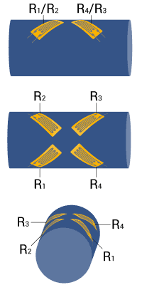 |
|
| Measurement of torsion strain | Full bridge
Four strain gauges are installed, each at an angle of 45° to the main axis as shown | + High output signal and excellent common mode rejection (CMR) + Temperature effects are well compensated |
| 14 | 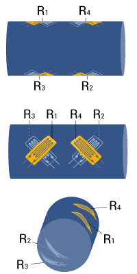 |
|
| Measurement of torsion strain with limited space for installation | Full bridge
Four strain gauges are installed as a full bridge, at an angle of 45° and superimposed (stacked rosettes) | + High output signal and excellent common mode rejection (CMR) + Temperature effects are well compensated |
| 15 | 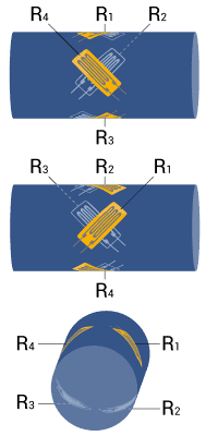 |
|
| Measurement of torsion strain with limited space for installation | Full bridge
Four strain gauges are installed as a full bridge at an angle of 45° and superimposed (stacked rosettes) | + High output signal and excellent common mode rejection (CMR) + Temperature effects are well compensated |
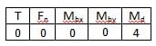
Note: A cylindrical shaft is assumed for torque measurement in example 13, 14, and 15. For reasons related to symmetry, bending in X and Y direction is allowed. The same conditions also apply for the bar with square or rectangular cross sections.
Explanations of the symbols:
| T | Temperature |
| Fn | Normal force |
| Mb | Bending moment |
| Mbx, Mby | Bending moment for X and Y directions |
| Md | Torque |
| εs | Apparent strain |
| εn | Normal strain |
| εb | Bending strain |
| εd | Torsion strain |
| ε | Effective strain at the point of measurement |
| ν | Poisson’s ratio |
| Active strain gauge | |
| Strain gauge for temperature compensation | |
| Resistor or passive strain gauge |
ひずみゲージは、より良い、より安全な製品を作るために、疲労を測定し、材料を試験するための重要な資産です。構造(Structural )耐久性試験、構造健全性モニタリング、OEMトランスデューサの製造のいずれにおいても、HBKの光学式および電気式ひずみゲージは第一の選択肢です。
HBKの光学式ひずみゲージラインnewLight は、長期安定性を向上させながら、大きなひずみ測定範囲を可能にします。設置が迅速かつ簡単で、湿度、錆、塩分などの環境条件に対する耐性があるため、構造(Structural)ヘルスモニタリングに最適です。

This will bring together HBM, Brüel & Kjær, nCode, ReliaSoft, MicroStrain and Discom brands, helping you innovate faster for a cleaner, healthier, and more productive world.