arrow_back_ios

Main Menu

arrow_back_ios

Main Menu

arrow_back_ios

Main Menu

Reduce Torque Measurement Doubt in Turbine Engine Testing

null

As part of this repurposing project, the goal was to create a test stand that would give the engineers the torque data they needed to make design changes that would help them optimize fuel efficiency. Acquiring accurate torque data on the engines’ performance is a critical part of this research. Although the firm had been converting jet engines to electrical power generators for many years, they recently decided to switch to in-line rotating torque sensors to improve their testing accuracy by minimizing torque measurement uncertainty.

The testing requirements called for torque sensors with full-scale capacity ranges of 200 N.m, 1 kN.m, 2 kN.m, and 130 kN.m. The three smaller capacity sensors had to share the same dimensional package size and operate at speeds up to 22,000 RPM. The largest torque sensor had to operate at up to 4,000 RPM. Like the rest of the test stand, the torque sensors used had to be extremely durable and reliable, given that a testing sequence might run anywhere from a few hours to a few months. Each sensor had to have two separate torque outputs to allow for greater confidence in data accuracy and to serve as a backup if one output failed during testing.

white paper pdf

null
Previously, the test stand had incorporated a non-rotating torque measurement technique that used a lever arm and a load cell attached to a floating or bearing-supported dynamometer (a large electric motor used a drive or a load) to measure reaction torque (Figure 1). The dynamometer was supported on either side by trunnion bearings. In this method, the lever arm is attached to the dynamometer, and the distance between the center of the shaft and the center of the load cell multiplied by the force equals torque.  Although it is a technique that has been around for more than half a century, there are some advantages to measuring reaction torque with a lever arm and load cell. For example, alignment is not critical because the sensor isn’t located on the rotating shaft.  Overload protection can be relatively simple to implement. In addition, the system is easy to calibrate because there’s no need to open the rotating shaft.
Despite these advantages, however, there are also some disadvantages associated with measuring reaction torque with a level arm and load cell. The first of these is low dynamic response (typically up to 20Hz) because the mass of the dynamometer acts as a low-pass filter, which increases the uncertainty in the torque measurement. In addition, the dynamometer must be supported on bearings, which can apply additional torque to the measurement because of friction; these bearings also demand regular maintenance.  The new torque measurement technique the client chose involved removing the lever arm and load cell, fixing the dynamometer in place so it no longer turned on the trunnion bearings, then adding an in-line torque sensor (Figure 2).  This technique employs a flange- to-flange style torque sensor using a digital telemetry
system, so it’s totally non-contact, with minimal backlash and support bearings. 
null
Measuring torque with an in-line torque sensor offers several advantages for this application. For example, it allows measuring the true dynamic torque in the rotating shaft more accurately and allows for higher dynamic response—up to 6kHz, rather than the 20Hz response common with the load cell and lever arm. With a foot-mounted dynamometer, the trunnion bearings and associated friction and maintenance issues are eliminated. Also, the in-line sensor provides greater dynamic torque measurement accuracy. Figure 3 shows a comparison of the signatures of the dynamic torque with the in-line sensor vs. the average torque.
null
Just as with the load cell and lever arm approach, there are disadvantages to measuring torque with an in-line torque sensor. Putting a torque sensor on a rotating shaft makes proper alignment critical and protecting against overloads is more difficult. When it’s time to calibrate the system, the process is more complicated, requiring modifications to the rotating shaft and/or removal of the torque sensor.null
Many different considerations go into the design and development of the rotating torque sensor for applications of this type. If the sensor’s rotor is made of titanium rather than steel, in-line torque sensors offer the advantage of lower weight. Combining titanium rotor construction with minimum end-to-end length can help to reduce the overall weight of the driveline, which can simplify avoiding “critical speeds” of the rotating shaft during the testing process. In essence, the critical speed is the point (as expressed in RPMs) at which a rotating shaft becomes unstable, that is, begins to vibrate harmonically. The goal is to create a driveline that is as short, stiff, and light in weight as possible in order to avoid unwanted vibrations and shaft run-out, which can increase measurement uncertainty as well as posing the potential for a catastrophic failure of the driveline. A growing number of in-line torque sensors use AC excitation on the strain gauge bridge, to improve the noise immunity of the torque measurement. 
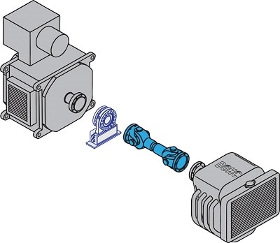
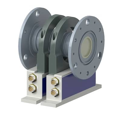
This helps to increase torque measurement accuracy, especially at very low torques. To address this customer’s testing requirements, the HBM torque sensor development staff soon decided a custom in-line torque sensor solution was necessary. Although there are many highly accurate standard
torque sensors on the market, the customer’s need for dual outputs, a customized length to match an existing coupling spacer, extremely high RPMs, and non-standard bolt pattern made a custom solution unavoidable (Figure 5). The final torque sensor featured a no-bearing design for less friction, and therefore, greater measurement accuracy, and reduced maintenance needs. Two strain gauge bridges with two stators were used to increase confidence in the accuracy of the torque measurement signal. Titanium rotor construction reduced the sensor’s weight and increased its RPM rating. Custom dimensions and a custom bolt pattern helped to reduce the length and weight of the driveline, and helped to move the critical speed to an area outside the sensor’s measurement range. The change from a lever arm and load cell sensor to an in-line torque sensor dramatically increased dynamic response as well as lowered the measurement uncertainty of the signal. With more reliable data on how changes to their engine design affect performance, the client can make more knowledgeable design decisions and increase the efficiency of their final product. Recently, the custom solution created for this customer has been standardized for use by others who need exceptionally high speed torque measurements combined with greater accuracy.
null