The electric motor has a very desirable torque speed curve because it can not only produce max torque at 0 speed, but across a wide range of speeds. While this ability creates new opportunities with the electric motor, it also creates some new challenges in comparison to internal combustion engines. One of these challenges is torque ripple, which has several implications including control, power output, noise, vibration, and durability. Torque ripple can be described as the variance of output torque as the motor rotates. This white paper will focus on the measurement of these signals and their implications for noise and vibration. The paper will also include examples from a couple of case studies which demonstrate the impact of torque ripple and its effects on NVH.
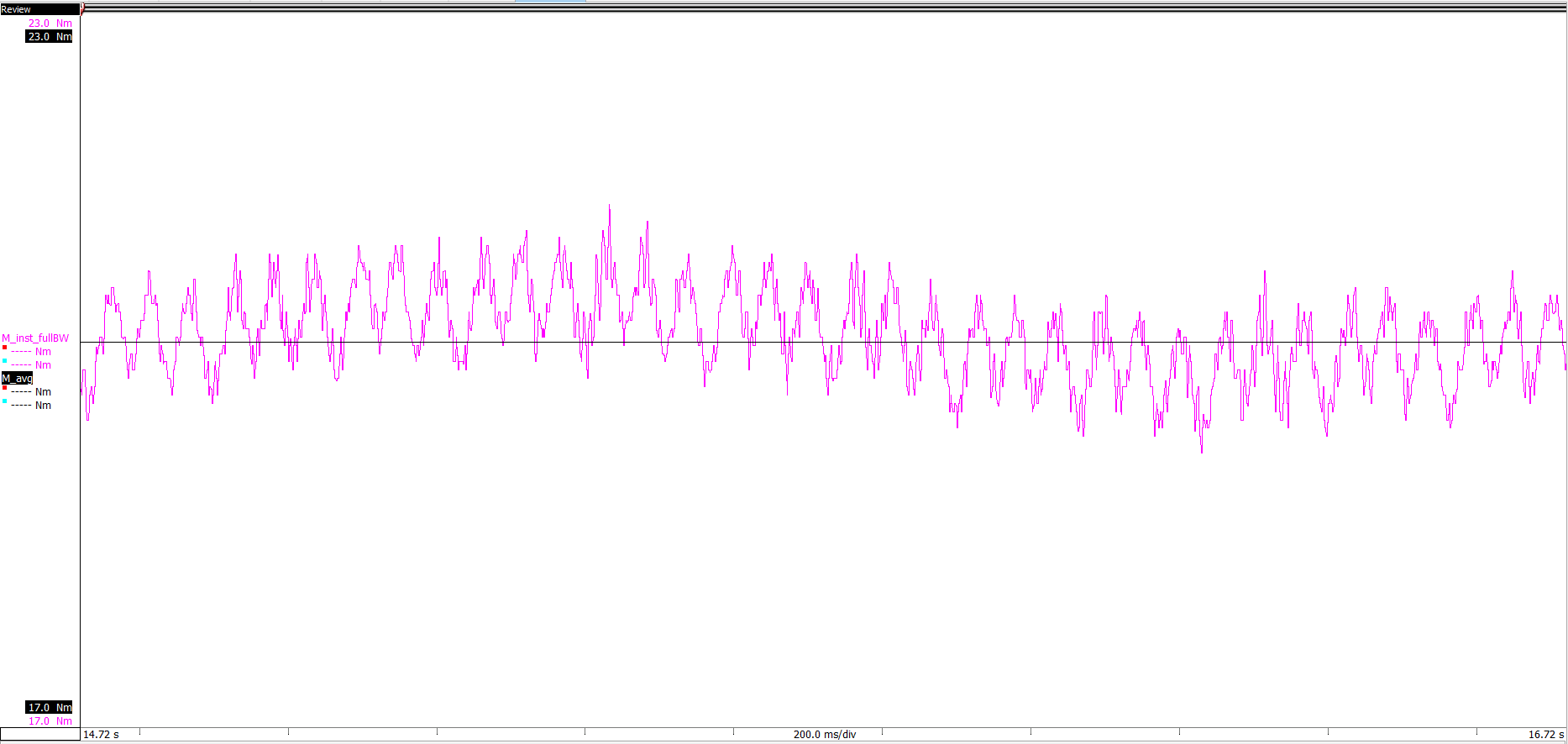
Torque is often described as a DC quantity, but it does have a frequency component. Specifically, in electric motors torque will have a DC average, with a cyclical offset. This offset will have a frequency that is a function of rotational speed and an amplitude that is a percentage of the DC value. An example of torque ripple can be seen in figure 1, where the average torque is a DC, but the high bandwidth torque shows a roughly +-2Nm ripple. While this may not seem like a significant issue, the high frequencies of this ripple can lead to a variety of undesirable outcomes; including audible noise, structural vibrations, and gear fatigue. In order to mitigate the torque ripple, we need to understand its sources which include electrical excitation, machine construction, mechanical resonances, alignment, and loading.
Electrical excitation of the machine contributes to the torque ripple because the torque of the machine will follow the current. The most extreme example of this is the single-phase machine where there will be cyclical torque at two-times the fundamental frequency, and a zero-torque element. By increasing the phases, you can eliminate the zero cross and amplitude of the ripple, but you will increase the frequency. The typical machine will have three phases, which is advantageous for torque ripple, but will not eliminate it.
Since the torque is created by the sinusoidal excitation, the torque ripple from excitation will be at the same frequency as the electrical signal, which means as speed increases, so will the torque ripple frequency. In addition, other elements of torque ripple will be present, because excitation is not a perfect sine wave. Inverters which operate at a high frequency are often employed, and the machine winding will affect the distribution of current. As a result, these issues will create additional torque ripple.
Construction is another example of a contributing factor which can impact torque ripple. In all machines torque ripple is driven by the machine winding function, and each machine type has a contribution of torque ripple form the rotor magnetics interacting with the stator iron. In induction machines, the torque ripple is smaller in amplitude and could be managed with the skew of the rotor bars. With an increase in the utilization of permanent magnet machines, you need to account for the effects of the magnets on the rotor, in addition to the winding function and skew. The magnets on the rotor will attract to the iron on the stator, and as the machine spins, the magnets will attract to each stator tooth. Since there are a fixed number of rotor magnets and stator slots, this element of torque ripple will also be proportional to speed. The high amplitude, and potentially high frequencies due to the speed of the machine make torque ripple from permanent magnets a difficult problem to characterize and reduce.
Given that excitation and the construction of the machine create torque ripple, you can also use these two features in combination to alleviate it. Different construction patterns combined with different types of machine control can be used to reduce torque ripple. Advances in feedback and inverter technology allow us to push the envelope of torque ripple mitigation. In order to validate that these methods of torque ripple mitigation work, engineers need to validate their designs with measurements.
Sign in now to download this white paper.
This will bring together HBM, Brüel & Kjær, nCode, ReliaSoft, MicroStrain and Discom brands, helping you innovate faster for a cleaner, healthier, and more productive world.
