arrow_back_ios

Main Menu

See All Acoustic End-of-Line Test Systems See All DAQ and instruments See All Electroacoustics See All Software See All Transducers See All Vibration Testing Equipment See All Academy See All Resource Center See All Applications See All Industries See All Insights See All Services See All Support See All Our Business See All Our History See All Our Sustainability Commitment See All Global Presence
arrow_back_ios

Main Menu

See All Actuators See All Combustion Engines See All Durability See All eDrive See All Production Testing Sensors See All Transmission & Gearboxes See All Turbo Charger See All Industrial electronics See All S&V Signal conditioner See All DAQ Systems See All Power Analyser See All S&V Hand-held devices See All High Precision and Calibration Systems See All Test Solutions See All nCode - Durability and Fatigue Analysis See All ReliaSoft - Reliability Analysis and Management See All Test Data Management See All DAQ Software See All Drivers & API See All Utility See All Vibration Control See All Acoustic See All Current / voltage See All Displacement See All Load Cells See All Pressure See All Strain Gauges See All Vibration See All Torque See All LDS Shaker Systems See All Vibration Controllers See All Power Amplifiers See All Accessories for Vibration Testing Equipment See All Training Courses See All Acoustics See All Asset & Process Monitoring See All Custom Sensors See All Data Acquisition & Analysis See All Durability & Fatigue See All Electric Power Testing See All NVH See All Reliability See All Smart Sensors See All Vibration See All Weighing See All Automotive & Ground Transportation See All Calibration See All Installation, Maintenance & Repair See All Support Brüel & Kjær See All Release Notes See All Compliance See All Our People
arrow_back_ios

Main Menu

See All QuantumX See All LAN-XI See All SomatXR See All MGCplus See All CANHEAD See All Optical Interrogators See All GenHS See All API See All Microphone Cartridges See All Microphone Sets See All Microphone Pre-amplifiers See All Sound Sources See All Acoustic Calibrators See All Special Microphones See All Accessories for acoustic transducers See All Experimental testing See All Transducer Manufacturing (OEM) See All CCLD (IEPE) accelerometers See All Charge Accelerometers See All Rotating See All Non-rotating (calibration) See All Electroacoustics See All Noise Source Identification See All Environmental Noise See All Sound Power and Sound Pressure See All Noise Certification See All Industrial Process Control See All Structural Health Monitoring See All Electrical Devices Testing See All Electrical Systems Testing See All Grid Testing See All High-Voltage Testing See All Vibration Testing with Electrodynamic Shakers See All Structural Dynamics See All Machine Analysis and Diagnostics See All Dynamic Weighing See All Calibration Services for Transducers See All Calibration Services for Handheld Instruments See All Calibration Services for Instruments & DAQ See All On-Site Calibration See All Resources See All Software License Management

Determine the Thermal Expansion Coefficient

In this article you will learn how the coefficient of thermal expansion of aluminium can be determined using "mismatched" foil strain gauges.

When there is a change in temperature, each strain gauge quarter bridge registers a measurement signal, the "apparent strain". The apparent strain of a strain gauge measuring point exposed to a temperature difference Δϑ, can be described as follows:

null

The following applies here:

ε                    Apparent strain of the strain gauge
α                    Temperature coefficient of the electrical resistance
αb                    Thermal expansion coefficient of the measurement object
αm                   Thermal expansion coefficient of the measuring grid material
k                       K factor of the strain gauge
Δϑ                    Temperature difference that triggers the apparent strain

On all of their strain gage packs, HBM shows the apparent strain as a function of temperature in a chart and also as a polynomial. Of course, these data only ever give useful results if the thermal coefficient of linear expansion of the material to be tested matches the data on the strain gage pack.

The following then applies:

null
null

Determining the Thermal Coefficient of Linear Expansion α

But the apparent strain can also be used perfectly well for measurement purposes, if the coefficient of thermal expansion αm is to be determined. In this situation, the following formula can be used:

null

Transposed, this produces:

null

ε                    Strain indicated at the amplifier
εm                     The strain triggered by the mechanical load
αDMS                Thermal coefficient of linear expansion as per the strain gauge pack

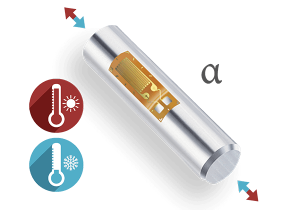
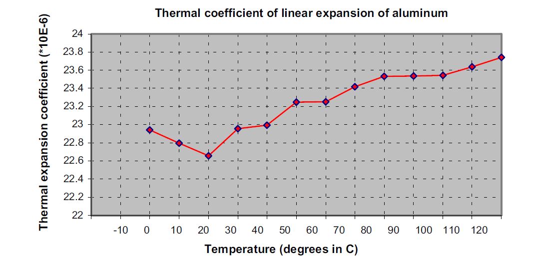
In a practical test, four HBM strain gauges of the LG11-6/350 type, adapted to steel (α=10.8 10-6/K), were installed on an aluminum workpiece. A four-wire circuit was used to eliminate cable influences. According to the data supplied by the manufacturer for the material, α=23.00 *10-6/K for T= 0 … 100°C.

ϑ (°C) εa(*10-6) εs(*10-6) εa-εs(*10-6) αb(*10-6)/K
-10 -396.9 -38.0 -358.9  
0 -254.4 -16.9 -237.5 22.9
10 -122.5 -5.0 -117.5 22.8
20 0 -1.1 1.1 22.7
30 118.8 -3.9 122.7 23.0
40 232.4 -12.2 244.6 23.0
50 344.3 -24.8 369.1 23.2
60 453.3 -40.3 493.6 23.3
70 562.1 -57.7 619.8 23.4
80 671.6 -75.6 747.2 23.5
90 781.8 -92.7 874.5 23.5
100 894.1 -107.9 1002.0 23.5
110 1010.5 -119.9 1130.3 23.6
120 1132.3 -127.4 1259.8 23.7

Tab. 1 Measurement results for a strain gauge adapted for ferrit. steel, installed on aluminum

null

If you calculate αm for the specified interval, you obtain 23.19 *10-6/K, which corresponds to a deviation from the theoretical value of 0.19 *10-6/K (0.84%).
To run the experiment, it is first necessary to install several strain gauges on the object under investigation (to attain experimental reliability). The sample must be flat in the direction of the measuring grid.

In the next step, the strains are determined subject to the temperature. Care must be taken to ensure that thermal equilibrium is established.
First εa-εs is calculated. To determine the thermal coefficient of linear expansion, you subtract the two calculated values (εa-εs ) from each other and divide this by the corresponding temperature interval. The coefficient of thermal expansion αDMS as per the pack data must then be added to this.

Example: In the interval from 20 to 40 degrees, the coefficient of thermal expansion is calculated as follows (using calculation shown in Formula 4):

null

During this measurement, the strain gauge creep is an undesirable effect. So in the interest of maximum accuracy, it is advisable to use HBM series K strain gauges, which have three different creep adjustments as standard and of these, use the strain gauge with the greatest end loop length.
Also, when the measuring temperatures are over 60 °C, it is advisable to use hot curing adhesives for installation.

Note: Subject to modifications. All product descriptions are for general information only. They are not to be understood as a guarantee of quality or durability.

Support Content