Reaction torque sensors are non-rotating torque sensors, which act similar to a lever arm and a load cell, without actually needing either.


A slip ring-style torque sensor was designed about 40 years ago. It uses graphite brushes that rub against silver alloy slip rings.

Rotary transformers are mechanically similar to the slip ring sensor. But electrically, it uses rotary transformers instead of using slip rings and brushes. One transformer is used to excite the torque sensor, and a second transformer is used to take the data back.


Clamp-on style torque sensors are ideal when it’s not feasible to break the shaft and install in an in-line torque sensor.

In the early 1990s, analog telemetry became reasonably cost effective and accurate.

Over the last five to ten years, digital telemetry became a more feasible way of making torque sensors. They are more high-tech than other sensors and have more advantages versus other torque sensors in the marketplace.


There are some vendors that offer dual-range torque sensors. HBM’s point of view is that these sensors are practically impossible to manufacture. In order to have a true dual-range torque sensor, it would have to have, for example, one 10,000 Newton meter bridge and one 1,000 newton meter bridge. If both of these bridges existed on the same torque sensor, once you put 10,000 Newton meters on it, you would twist and destroy the smaller bridge. It's virtually impossible to mechanically overload-protect a torque sensor in order to protect the smaller capacity bridge. So, typically one or two 10,000 newton meter bridges are used offering a separate calibration for the 1,000 newton meter range. Typically, there is also a voltage gain added to increase the output from the smaller strain gauge bridge. Filtering is then applied to clean up the noise, which can have an adverse effect on accuracy and measuring at the low end. Ultimately it’s not highly possible to manufacture a true dual-range torque sensor. However, you can use some digital torque sensors with software and configure them to act as a dual-range torque sensor.
Measurement accuracy, or level of uncertainty, is a key consideration when selecting a torque sensor because different applications require different levels of uncertainty. For example:
How do you quantify the measurement uncertainty of a torque sensor? While it can be complicated, a sensor’s uncertainty generally has six components:
You can use a measurement uncertainty formula (see image 10) to estimate an uncertainty number using data from a torque sensor’s data sheet. Factored into a sensor’s uncertainty is its calibration data. So, it's important to know what type of calibration equipment your vendor uses and how uncertain is the calibration equipment. In some countries, torque is not always a completely controlled measurement, so the vendor becomes responsible for assuring you, the customer, of the accuracy of its lab. One can weigh the weights, measure the arm, and calibrate the instrumentation, but in some areas of the world there is no controlling entity to ensure that the procedures are consistent among vendors—or even that the equipment is working properly. In some countries, there are governing organizations that control torque measurement. In Germany, the PTB (similar to the National Institute of Standards and Technology) verifies the accuracy of the lab calibration equipment and issues a certification. By choosing a vendor with this type of certification, you can be more confident in the data on a torque sensor’s calibration datasheet.

When evaluating torque sensors, it’s important to consider your application’s response-time requirements as well as the ratio between the sampling rate and response time to avoid aliasing. Some torque sensors have a 3:1, 6:1 or even a 12:1 ratio, such as the HBM T12. These high response times will allow you to measure torsional vibrations.

Torque sensors are basically antennas - they have wires and coils inside, so proper cabling, shielding and grounding is critical. Find out what kind of signal conditioning is being used on the torque sensor. Is it AC or DC excitation across the Wheatstone bridge? At HBM, we generally recommend AC strain gauge conditioning because it’s more noise-immune than DC strain gauge conditioning. It minimizes the errors that DC can cause due to thermal or 1F noise sources.


Modern torque sensors are designed to be torsionally stiff with higher frequency response times. This gives the end user a greater capability to measure dynamic torque. Image 14 illustrates a diesel-engine torque measured on a dynamometer that has an in-line torque sensor as well as a lever arm and load cell. If the frequency of the oscillating torque is higher than the natural frequency of the dynamometer, then the lever arm configuration can act as a mechanical low-pass filter, generally around 20Hz. In this signature, the lever arm load cell (in blue) gives a filtered, average torque signal; whereas, the in-line torque sensor (in red) gives you a more dynamic torque signal - this is the advantage of the rotating torque sensor: its measurement, or the signal, is more dynamic. When a shaft starts to spin, a number of effects can occur that will influence the torque sensor and its ability to read torque correctly. Dynamic considerations should include rotational effects, critical speeds and extraneous loads.

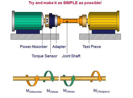
To help eliminate critical speeds of a rotating shaft, a perfect torque sensor would weigh nothing, have infinite stiffness and have no length at all. While this is of course impossible, a vendor should aim to manufacture a torque sensor as stiff as possible, as light as possible and as short as possible. At a specific RPM, the shaft will want to become unstable, and when critical, the shaft will act as a sine wave or vibrate. Once the shaft becomes unstable, the torque sensor is susceptible to mechanical failure, such as cracking into two pieces. So, it's always good to do a torsional analysis of your rotating shaft before using the test stand. HBM recommends making your test stand as simple as possible. The fewer the parts, the fewer opportunities there are for error. Once you choose the right torque sensor for your needs, learn more about installing it in HBM’s “21 Tips on How to Install a Torque Sensor” white paper. It’s a good idea to keep most of the torque sensors’ weight as close to a bearing block as possible in the test stand. In image 15, the torque sensor and the coupling are close to the dynamometer - in this case, an electric motor - on the left. By keeping the majority of the weight close to a bearing block, you can move your critical speed outside of the measurement range and help to prevent a catastrophic situation.
Parasitic loads are axial forces, lateral limit forces and bending moment forces that occur when the shaft is spinning. These off axis forces can add a very large error to a rotating torque sensor, just like temperature changes. Eliminating these forces will help you increase the accuracy, or lower the uncertainty, of your test stand. The supplier of the torque sensor can help you to understand these parasitic forces, how they affect the torque sensor, and how much error you can expect when these forces are applied to the torque sensor. Most manufacturers give parasitic forces limits on their datasheets. While these limits generally aren't catastrophic, the maximum of these limits can start to affect the output of the torque sensor. Typically, if you reach 100 percent of the combined parasitic force limits, you can expect a .3 percent of full-scale error on your torque sensor. So, minimizing the parasitic loading in the application is important.

This will bring together HBM, Brüel & Kjær, nCode, ReliaSoft, MicroStrain and Discom brands, helping you innovate faster for a cleaner, healthier, and more productive world.
