arrow_back_ios

Main Menu

See All Acoustic End-of-Line Test Systems See All DAQ and instruments See All Electroacoustics See All Software See All Transducers See All Vibration Testing Equipment See All Academy See All Resource Center See All Applications See All Industries See All Insights See All Services See All Support See All Our Business See All Our History See All Our Sustainability Commitment See All Global Presence
arrow_back_ios

Main Menu

See All Actuators See All Combustion Engines See All Durability See All eDrive See All Production Testing Sensors See All Transmission & Gearboxes See All Turbo Charger See All DAQ Systems See All High Precision and Calibration Systems See All Industrial electronics See All Power Analyser See All S&V Hand-held devices See All S&V Signal conditioner See All Test Solutions See All DAQ Software See All Drivers & API See All nCode - Durability and Fatigue Analysis See All ReliaSoft - Reliability Analysis and Management See All Test Data Management See All Utility See All Vibration Control See All Acoustic See All Current / voltage See All Displacement See All Load Cells See All Pressure See All Strain Gauges See All Torque See All Vibration See All Accessories for Vibration Testing Equipment See All Power Amplifiers See All LDS Shaker Systems See All Vibration Controllers See All Training Courses See All Acoustics See All Asset & Process Monitoring See All Custom Sensors See All Data Acquisition & Analysis See All Durability & Fatigue See All Electric Power Testing See All NVH See All Reliability See All Smart Sensors See All Vibration See All Weighing See All Automotive & Ground Transportation See All Calibration See All Installation, Maintenance & Repair See All Support Brüel & Kjær See All Release Notes See All Compliance See All Our People
arrow_back_ios

Main Menu

See All CANHEAD See All GenHS See All LAN-XI See All MGCplus See All Optical Interrogators See All QuantumX See All SomatXR See All BK Connect / Pulse See All API See All Accessories for acoustic transducers See All Acoustic Calibrators See All Microphone Cartridges See All Microphone Pre-amplifiers See All Microphone Sets See All Sound Sources See All Special Microphones See All Experimental testing See All Transducer Manufacturing (OEM) See All Non-rotating (calibration) See All Rotating See All CCLD (IEPE) accelerometers See All Charge Accelerometers See All Electroacoustics See All Noise Source Identification See All Environmental Noise See All Sound Power and Sound Pressure See All Noise Certification See All Industrial Process Control See All Structural Health Monitoring See All Electrical Devices Testing See All Electrical Systems Testing See All Grid Testing See All High-Voltage Testing See All Vibration Testing with Electrodynamic Shakers See All Structural Dynamics See All Machine Analysis and Diagnostics See All Dynamic Weighing See All Calibration Services for Transducers See All Calibration Services for Handheld Instruments See All Calibration Services for Instruments & DAQ See All On-Site Calibration See All Resources See All Software License Management
The Wheatstone Bridge Circuit

null

The Wheatstone bridge can be used in various ways to measure electrical resistance:

  • For the determination of the absolute value of a resistance by comparison with a known resistance
  • For the determination of relative changes in resistance

The latter method is used with regard to strain gauge techniques. It enables relative changes of resistance in the strain gauge, which are usually around the order of 10-4 to 10-2 Ω/Ω to be measured with great accuracy.

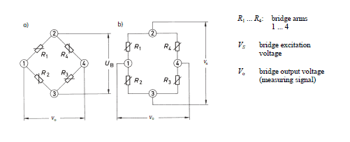
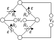
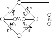
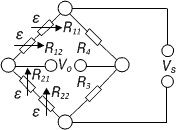
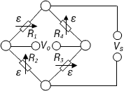
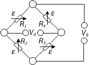
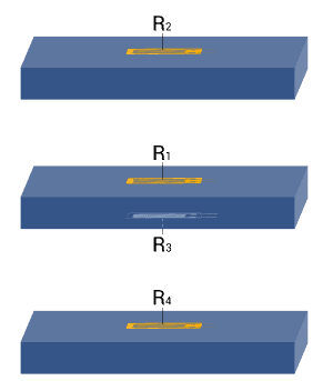
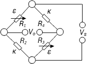
The image below shows two different illustrations of the Wheatstone bridge which are electrically identical: figure a) shows the usual rhombus representation in which the Wheatstone is used; and figure b) is a representation of the same circuit, which will be clearer for an electrically untrained person.

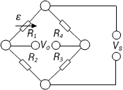
The four arms or branches of the bridge circuit are formed by the resistances R1 to R4. The corner points 2 and 3 of the bridge designate the connections for the bridge excitation voltage Vs. The bridge output voltage V0 , that is the measurement signal, is available on the corner points 1 and 4.

Note: There is no generally accepted rule for the designation of the bridge components and connections. In existing literature, there are all kinds of designations and this is reflected in the bridge equations. Therefore, it is essential that the designations and indices used in the equations are considered along with their positions in the bridge networks in order to avoid misinterpretation.
null

The bridge excitation is usually an applied, stabilized direct, or alternating voltage Vs. If a supply voltage Vs is applied to the bridge supply points 2 and 3, then the supply voltage is divided up in the two halves of the bridge R1, R2 and R4, R3 as a ratio of the corresponding bridge resistances, i.e., each half of the bridge forms a voltage divider.

The bridge can be imbalanced, owing to the difference in the voltages from the electrical resistances on R1, R2 and R3, R4. This can be calculated as follows:

null
if the bridge is balanced and
null
where the bridge output voltage V0 is zero. With a preset strain, the resistance of the strain gauge changes by the amount ΔR. This gives us the following equation:
null

For strain measurements, the resistances R1 and R2 must be equal in the Wheatstone bridge. The same applies to R3 and R4.

With a few assumptions and simplifications, the following equation can be determined (further explanations are given in the HBM book 'An Introduction to Measurements using Strain Gauges'):

null
In the last step of calculation, the term ΔR/R must be replaced by the following:
null
Here k is the k-factor of the strain gauge, ε is the strain. This gives us the following:
null
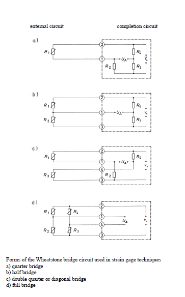
The equations assume that all the resistances in the bridge change. For instance, this situation occurs in transducers or with test objects performing similar functions. In experimental tests, this is hardly ever the case and usually only some of the bridge arms contain active strain gauges, the remainder consisting of bridge completion resistors. Designations for the various forms, such as quarter bridge, half bridge, double quarter or diagonal bridge and full bridge, are commonplace.
OLYMPUS DIGITAL CAMERA

Book: An Introduction to Measurements using Strain Gauges

Get a complete overview of the topic of "An Introduction to Measurements using Strain Gauges" - in Karl Hofmann's #1 reference book on stress analysis using strain gauges. In this 250-page, richly illustrated book, Karl Hoffmann describes, in plain language, the fundamentals of strain gauge measurement, ranging from gauge selection through analysis and evaluation of acquired data. Take a look at the book!

null

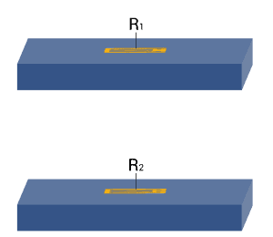
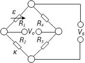
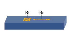
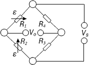
Depending on the measurement task one or more strain gauges are used at the measuring point. Although designations such as full bridge, half bridge, or quarter bridge are used to indicate such arrangements, actually they are not correct. In fact, the circuit used for the measurement is always complete and is either fully or partially formed by the strain gauges and the specimen. It is then completed by fixed resistors, which are incorporated within the instruments.  

Transducers generally have to comply with more stringent accuracy requirements than measurements pertaining to experimental tests. Therefore, transducers should always have a full bridge circuit with active strain gauges in all four arms.

Full bridge or half bridge circuits should also be used for stress analysis if different kinds of interferences need to be eliminated. An important condition is that cases of different stresses are clearly distinguished, such as compressive or tensile stress, as well as bending, shear, or torsional forces.

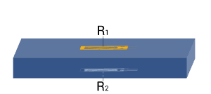
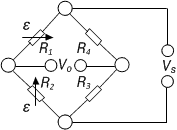
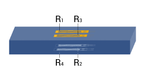
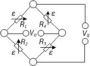
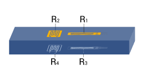
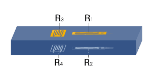
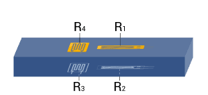
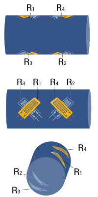
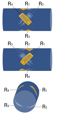
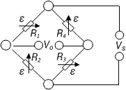
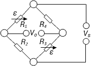
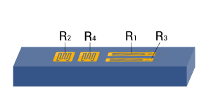
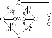
The table below shows the dependence of the geometrical position of the strain gauges, the type of bridge circuit used and the resulting bridge factor B for normal forces, bending moments, torque and temperatures. The small tables given for each example specify the bridge factor B for each type of influencing quantity. The equations are used to calculate the effective strain from the bridge output signal VO/VS.


Bridge configuration

External impacts measured:

Application

Description

Advantages and disadvantages

1

Strain measurement on a tension/ compression bar

Strain measurement on a bending beam
Simple quarter bridge

Simple quarter bridge circuit with one active strain gauge
+ Easy installation

- Normal and bending strain are superimposed

- Temperature effects not automatically compensated
2


Strain measurement on a tension/ compression bar

Strain measurement on a bending beam
Quarter bridge with an external dummy strain gauge

Two quarter bridge circuits, one actively measures strain, the other is mounted on a passive component made of the same material, which is not strained
+ Temperature effects are well compensated

- Normal and bending strain cannot be separated (superimposed bending)
3


Strain measurement on a tension/ compression bar

Strain measurement on a bending beam
Poisson half-bridge

Two active strain gauges connected as a half bridge, one of them positioned at 90° to the other
+ Temperature effects are well compensated when material is isotrop
4


Strain measurement on a bending beam Half bridge

Two strain gauges are installed on opposite sides of the structure
+ Temperature effects are well compensated

+ Separation of normal and bending strain (only the bending effect is measured)
5


Strain measurement on a tension/ compression bar Diagonal bridge

Two strain gauges are installed on opposite sides of the structure
+ Normal strain is measured independently of bending strain (bending is excluded)
6


Strain measurement  on a tension/ compression bar

Strain measurement on a bending beam
Full bridge

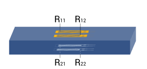
4 strain gauges are installed on one side of the structure as a full bridge
+ Temperature effects are well compensated

+ High output signal and excellent common mode rejection (CMR)

- Normal and bending strain cannot be separated (superimposed bending)
7


Strain measurement on a tension/ compression bar Diagonal bridge with dummy gauges

Two active strain gauges, two passive strain gauges
+ Normal strain is measured independently of bending strain (bending is excluded)

+ Temperature effects are well compensated
8


Strain measurement on a bending beam Full bridge

Four active strain gauges are connected as a full bridge
+ Separation of normal and bending strain (only the bending effect is measured)

+ High output signal and excellent common mode rejection (CMR)

+Temperature effects are well compensated
9


Strain measurement on a tension/ compression bar Full bridge

Four active strain gauges, two of them rotated by 90°
+ Normal strain is measured independently of bending strain (bending is excluded)

+ Temperature effects are well compensated

+ High output signal and excellent common mode rejection (CMR)
10


Strain measurement on a bending beam Full bridge

Four active strain gauges, two of them rotated by 90°
+ Separation of normal and bending strain (only the bending effect is measured)

+ Excellent common mode rejection (CMR)

+ Temperature effects are well compensated
11

Strain measurement on a bending beam Full bridge

Four active strain gauges, two of them rotated by 90°
+ Separation of normal and bending strain (only the bending effect is measured)

+ High output signal and excellent common mode rejection (CMR)

+ Temperature effects are well compensated
12


Strain measurement on a bending beam Half bridge

Four active strain gauges connected as a half bridge
+ Separation of normal and bending strain (only the bending effect is measured)

+ Temperature effects are well compensated

+ High output signal and excellent common mode rejection (CMR)
13          

Measurement of torsion strain Full bridge

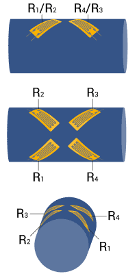
Four strain gauges are installed, each at an angle of 45° to the main axis as shown
+ High output signal and excellent common mode rejection (CMR)

+ Temperature effects are well compensated
14                     

Measurement of torsion strain with limited space for installation Full bridge

Four strain gauges are installed as a full bridge, at an angle of 45° and superimposed (stacked rosettes)
+ High output signal and excellent common mode rejection (CMR)

+ Temperature effects are well compensated
15                       

Measurement of torsion strain with limited space for installation Full bridge

Four strain gauges are installed as a full bridge at an angle of 45° and superimposed (stacked rosettes)
+ High output signal and excellent common mode rejection (CMR)

+ Temperature effects are well compensated

Note: A cylindrical shaft is assumed for torque measurement in example 13, 14, and 15. For reasons related to symmetry, bending in X and Y direction is allowed. The same conditions also apply for the bar with square or rectangular cross sections.

Explanations of the symbols:

T Temperature
Fn Normal force
Mb Bending moment
Mbx, Mby Bending moment for X and Y directions
Md Torque
εs Apparent strain
εn Normal strain
εb Bending strain
εd Torsion strain
ε Effective strain at the point of measurement
ν Poisson’s ratio
Active strain gauge
Strain gauge for temperature compensation
Resistor or passive strain gauge

Read our technical articles

Title / DescriptionLanguage
Anwendung der Wheatstone'schen Brückenschaltung - Technische InformationEnglish
Applying the Wheatstone Bridge Circuit - Technical InformationEnglish
Structural integration of strain gagesEnglish
Sensing of Surface Strain with Flexible Fiber Bragg Strain GagesEnglish
TECH NOTE - QuantumX and catman AP for electrical power analysisEnglish
TECH NOTE - IEEE1588:2008 PTPv2-Switches and Grandmaster ClocksEnglish
TECH NOTE - QuantumX Data Recorder and GPS / GNS / IMUEnglish
TECH NOTE - IEEE1588:2008 Precision Time Protocol in Data Acquisition and TestingEnglish
TECH NOTE - QuantumX und Mehr-Komponenten-AufnehmerEnglish
TECH NOTE - QuantumX Data Recorder and Video Camera integrationEnglish
TECH NOTE - QuantumX MX430B Precision Bridge Module: real-time functionalityEnglish
TECH NOTE - Analog to Digital Data Path in QuantumX ModulesEnglish
TECH NOTE - Noise Analysis using QuantumX and catmanAP English
TECH NOTE - QuantumX Data Recorder operated by Apple’s iPadEnglish
TECH NOTE - 3rd Party Device Integration into catmanAP or QuantumX Data Recorder CX22B‐W English
TECH NOTE - Using the QuantumX Data Recorder CX22B-W as GatewayEnglish
T12HP - Interface description / SchnittstellenbeschreibungEnglish
TechNote - FDT/DTM ApplicationEnglish
ClipX TechNotesEnglish
TechNote PCB Strain MeasurementEnglish
TechNote PCB Strain MeasurementDeutsch
TT-3/100: Einsatz von Foliensensoren zur TemperaturmessungEnglish
TT-3/100: Using Foil Sensors for Temperature MeasurementEnglish
Anwendung der Wheatstone'schen Brückenschaltung - Technische InformationEnglish
Applying the Wheatstone Bridge Circuit - Technical InformationEnglish
Full-Bridge-Strain-Gauge Access Points - Technical InformationEnglish
Voll-Brücken-DMS Anschlusspunkte - Technische InformationDeutsch
Professional documentation of a Strain Gauge Installation - Technical InfoEnglish
Professionelle Dokumentation einer DMS-Installation - Technische InfoDeutsch
Solder terminals (self-adhesive) - Technical InformationEnglish
Lötstützpunkte (selbstklebend) - Technische InformationDeutsch
Determine the thermal expansion coefficientEnglish
Wärmeausdehnungskoeffizient bestimmenEnglish
TECH NOTE - catmanAP script based transmitting of CAN messagesEnglish
TECH NOTE: Integrated Electronics Piezo-Electric Sensing (IEPE)English
Tech Note: Very slow sample rates in catmanEnglish
Tech Note - Gauge Factor DeviationEnglish
TECH NOTE: QuantumX Integration into ControlDesk from dSPACEEnglish
SB02A - Control DrawingEnglish
SB01A - Control DrawingEnglish
SD01A - Control DrawingEnglish
TECH NOTE - catman WebServerEnglish
Tech Note: MGCplus Shunt CalibrationEnglish
Tech Note: Gom Aramis Integration in catmanEnglish
Tech Note: QuantumX-catmanAP Noise AnalysisEnglish
Tech Note: catman AP script based transmitting of CAN messagesEnglish
Tech Note: QuantumX Crash TestingEnglish
Tech Note: QuantumX catman AP - Signal AnalysisEnglish
Tech Note - catman Easy VideocamEnglish
TECH NOTE: QuantumX / SomatXR Integration into CANapeEnglish
TECH NOTE: Integrating GPS / GNSS / IMU Sensors into QuantumX Data Recorder for Mobile Data Acquisition and Map Based Data AnalysisEnglish
TECH NOTE - Highly Accurate and Dynamic Temperature Measurement With ThermocouplesEnglish
TECH NOTE: Using WLAN in large scale measurement and telemetry applicationsEnglish
QuantumX und Mehrkomponenten-Aufnehmer (MCS)English
QuantumX and Multi-Component Sensors (MCS)English
eDAQXR / eDAQXR-lite - External Fuse UsageEnglish
SomatXR - Tech NotesEnglish
Tech Note: Strain Measurement on PCBs with catmanEnglish
TECH NOTE: Integrating GPS / GNSS / IMU Sensors into QuantumX or SomatXR Data Recorder for Mobile Data Acquisition and Map Based Data AnalysisEnglish
TechNotesEnglish
WTX120 Example Profinet ProjectEnglish
PMX TechNotesEnglish
DSE Tech NotesEnglish
PMX Tech NotesEnglish
Temperature compensation with FBG sensorsEnglish
Temperature compensation in catmanEnglish
X60 - Technical InformationEnglish
X60 - Technische InformationDeutsch
WTX120 Example Profinet ProjectEnglish
AED/FIT - Operating InformationEnglish
AED/FIT - AnwendungsinformationDeutsch
Integrating Kistler RoaDyn® Wheel Force Transducers into QuantumX / SomatXR Data RecorderEnglish

Support Content