arrow_back_ios
Main Menu
arrow_back_ios
Main Menu
- Accessories
- Actuators
- Combustion Engines
- Durability
- eDrive
- Mobile Systems
- Production Testing Sensors
- Transmission Gearboxes
- Turbo Charger
- DAQ Systems
- High Precision and Calibration Systems
- Industrial electronics
- Power Analyser
- S&V Hand-held devices
- S&V Signal conditioner
- Wireless DAQ Systems
- Head and torso simulators (HATS)
- Artificial ears
- Electroacoustic hardware
- Bone conduction
- Electoacoustic software
- Accessories old
- Pinnae
- Accessories
- DAQ
- Drivers API
- nCode - Durability and Fatigue Analysis
- ReliaSoft - Reliability Analysis and Management
- Test Data Management
- Utility
- Vibration Control
- Inertial Sensor Software
- Acoustic
- Current / voltage
- Displacement
- Force
- Inertial Sensors
- Load Cells
- Multi Component Sensors
- Pressure
- Strain
- Temperature Sensors
- Tilt Sensors
- Torque
- Vibration
- Exciters
- Articles
- Case Studies
- Recorded Webinars
- Presentations
- Primers and Handbooks
- Videos
- Whitepapers
- Search all resources
- Acoustics
- Asset & Process Monitoring
- Custom Sensors
- Data Acquisition & Analysis
- Durability & Fatigue
- Electric Power Testing
- Machine automation control and navigation
- NVH
- Reliability
- Smart Sensors
- Vibration
- Virtual Testing
- Weighing
- Aerospace & Defence
- Audio
- Automotive & Ground Transportation
- Energy
- Robotics
- Vibration testing - Industries
- Calibration
- HBK Assured Service Contracts
- Installation, Maintenance & Repair
- Fatigue Testing Lab & Materials Characterisation - HBK
arrow_back_ios
Main Menu
- Bridge Calibration Units
- Microphone Calibration System
- Sound Level Meter Calibration System
- Strain Gauge Precision Instrument
- Vibration Transducer Calibration System
- Accessories
- BK Connect Pulse
- catman Enterprise
- catmanEasy AP
- Software Downloads for Perception / Genesis HighSpeed
- Tescia
- ReliaSoft BlockSim
- ReliaSoft Cloud
- ReliaSoft Lambda Predict
- ReliaSoft Product Suites
- ReliaSoft RCM++
- ReliaSoft XFMEA
- ReliaSoft XFRACAS
- ReliaSoft Weibull++
- Classical Shock
- Random
- Random-On-Random
- Shock Response Spectrum Synthesis
- Sine-On-Random
- Time Waveform Replication
- Vibration Control Software
- Microphone sets
- Cartridges
- Reference Microphones
- Special Microphones
- Acoustic Material Testing Kits
- Acoustic Calibrators
- Hydrophones
- Microphone Pre-amplifiers
- Sound Sources
- Accessories for acoustic transducers
- Inertial Measurement Units (IMU)
- Vertical Reference Units (VRU)
- Attitude and Heading Reference Systems (AHRS)
- Inertial Navigation Systems (INS)
- Inertial Sensors Accessories
- Bending / beam
- Canister
- Compression
- Single Point
- Tension
- Weighing Modules
- Digital load cells
- Accessories
- Accessories
- Experimental testing
- Fiber Optic Technology
- Transducer Manufacturing (OEM)
- Strain Sensors
- Accessories
- CCLD (IEPE) accelerometers
- Charge Accelerometers
- Fiber Optic Accelerometers
- Force transducers
- Reference accelerometers
- Impulse hammers / impedance heads
- Tachometer Probes
- Vibration Calibrators
- Cables
- Accessories
- Acoustics and Vibration
- Asset & Process Monitoring
- Data Acquisiton
- Electric Power Testing
- Fatigue and Durability Analysis
- Mechanical Test
- Reliability
- Weighing
- Electroacoustics
- Noise Source Identification
- Handheld S&V measurements
- Sound Power and Sound Pressure
- Noise Certification
- Acoustic Material Testing
- OEM Custom Sensor Assemblies for eBikes
- OEM Custom Sensor Assemblies for Agriculture Industry
- Custom Sensor Assemblies for Robotic OEM
- OEM Custom Sensor Assemblies for Medical
- Automotive Structural Durability and Fatigue Testing
- Durability Simulation & Analysis
- Material Fatigue Characterisation
- Electrical Devices Testing
- Electrical Systems Testing
- Grid Testing
- High-Voltage Testing
- End of Line Durability Testing
- Process Weighing
- Sorting and Batching Solutions
- Scale Manufacturing Solutions
- Vehicle Scale Solutions
- Filling, Dosing and Checkweighing Control
- Agricultural Robots
- Collaborative Robots (Cobots)
- Industrial Robots
- Medical, Surgical, & Healthcare Robots
- Mobile Robots
arrow_back_ios
Main Menu
- Housing
- Communication processor
- Amplifier modules
- Connection boards
- Special function modules
- Accessories
- G-Link-200
- G-Link-200-OEM
- SG-Link-200
- SG-Link-200-OEM
- V-Link-200
- RTD-Link-200
- TC-Link-200
- TC-Link-200-OEM
- Free-field Microphone Cartridges
- Pressure-field Microphone Cartridges
- Diffuse-field Microphone Cartridges
- Binaural Audio
- Outdoor microphones
- Probe Microphones
- Sound intensity probes
- Surface microphone
- Array microphones
- Other special microphone
- Production line test
- Microphone cables
- Tripods
- Microphone booms
- Microphone adapters
- Electroacoustic actuators
- Microphone Windscreens
- Nose cones
- Microphone holders
- Tripods
- Other accessories for acoustic transducers
- Microphone outdoor protection
- Rod end bearings
- Tensile load introductions
- Thrust pieces and load buttons
- Cables and connectors
- Screw sets
- Load base / Tensile compressive adapter
- Measurement Cables
- Ground cables
- Thrust pieces
- Bearings
- Load feet
- Base plates
- Knuckle eyes
- Adapters
- Mouting aids and others
- Adhesives
- Protective coatings
- Cleaning material
- SG Kits
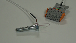
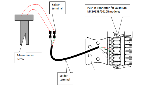
- Solder terminals
- Other
- Cables
- ZeroPoint Balancing
- TCS balancing
- TCO balancing
- Magnets
- Mounting clips/bases
- Studs, screws and washers
- Adhesives/Tools
- Adapters
- Mechanical filters
- Other accessories
- Testing Of Hands-Free Devices
- Smart Speaker Testing
- Speaker Testing
- Hearing Aid Testing
- Headphone Testing
- Soundbar Testing
- Telephone Headset And Handset Testing
- Acoustic Holography
- Acoustic Signature Management
- Underwater Acoustic Ranging
- Wind Tunnel Acoustic Testing – Aerospace
- Wind Tunnel Testing For Cars
- Beamforming
- Flyover Noise Source Identification
- Real-Time Noise Source Identification With Acoustic Camera
- Sound Intensity Mapping
- Spherical Beamforming
- Product Noise
- Shock and Drop Testing
- Environmental Stress Screening - ESS
- Package Testing
- Buzz, Squeak and Rattle (BSR)
- Mechanical Satellite Qualification - Shaker Testing
- Operating Deflection Shapes (ODS)
- Classical Modal Analysis
- Ground Vibration Test (GVT)
- Operational Modal Analysis (OMA)
- Structural Health Monitoring (SHM)
- Test-FEA Integration
- Shock Response Spectrum (SRS)
- Structural Dynamics Systems
- Force Calibration
- Torque Calibration
- Microphones & Preamplifiers Calibration
- Accelerometers Calibration
- Pressure Calibration
- Displacement Sensor Calibration
- Sound Level Meter Calibration
- Sound Calibrator & Pistonphone Calibration
- Vibration Meter Calibration
- Vibration Calibrator Calibration
- Noise Dosimeter Calibration
- QuantumX Calibration
- Genesis HighSpeed Calibration
- Somat Calibration
- Industrial Electronics Calibration
- LAN-XI Calibration