
Introduction to Reliability Block Diagrams Using ReliaSoft BlockSim
Read More
Software Used: BlockSim
[Please note that the following article — while it has been updated from our newsletter archives — may not reflect the latest software interface and plot graphics, but the original methodology and analysis steps remain applicable.]
Fault trees and reliability block diagrams are both symbolic analytical logic techniques that can be applied to analyze system reliability and related characteristics. Although the symbols and structures of the two diagram types differ, most of the logical constructs in a fault tree diagram (FTD) can also be modeled with a reliability block diagram (RBD). You can use either diagram type or combinations of both in your BlockSim analyses.
This article presents a brief introduction to fault tree analysis concepts, illustrates the similarities between fault tree diagrams and reliability block diagrams and introduces some of BlockSim's fault tree capabilities.
Bell Telephone Laboratories developed the concept of fault tree analysis in 1962 for the U.S. Air Force for use with the Minuteman system. It was later adopted and extensively applied by the Boeing Company. A fault tree diagram follows a top-down structure and represents a graphical model of the pathways within a system that can lead to a foreseeable, undesirable loss event (or a failure). The pathways interconnect contributory events and conditions using standard logic symbols (AND, OR etc).
Fault tree diagrams consist of gates and events connected with lines. The AND and OR gates are the two most commonly used gates in a fault tree. To illustrate the use of these gates, consider two events (called "input events") that can lead to another event (called the "output event"). If the occurrence of either input event causes the output event to occur, then these input events are connected using an OR gate.
Alternatively, if both input events must occur in order for the output event to occur, then they are connected by an AND gate. Figure 1 shows a simple fault tree diagram in which either A or B must occur in order for the output event to occur. In this diagram, the two events are connected to an OR gate.
Figure 1: Fault tree where either A or B can occur
If the output event is system failure and the two input events are component failures, then this fault tree indicates that the failure of A or B causes the system to fail. The RBD equivalent for this configuration is a simple series system with two blocks, A and B, as shown next.

In this webinar, explore how ReliaSoft BlockSim helps optimize maintenance costs, perform sensitivity analysis, and plan scenarios across various industries. Learn how BlockSim forecasts real-life scenarios, helping you analyze and identify bottlenecks to balance availability with cost efficiency and improve maintenance management.
Gates are the logic symbols that interconnect contributory events and conditions in a fault tree diagram. In addition to the AND and OR gates described above, fault trees can also logically connect events with other gates, such as the Voting OR gate, in which the output event occurs if a certain number of the input events occur (i.e., k-out-of-n redundancy), the Sequence Enforcing gate, in which the output event occurs if all events occur in a specific sequence, etc. An event (or a condition) in a fault tree is similar to a standard block in an RBD in that it can be associated with a probability of occurrence (or a distribution function). However, fault trees also use several graphical symbols to represent different types of events. For example, a circle typically represents a basic initiating event in a fault tree diagram, while a pentagon represents an event that is normally expected to occur. All events are treated the same from an analytical perspective.
Table 1 shows the gate symbols that are used in classic fault tree analysis and Table 2 shows the event symbols. For both tables, the reliability block diagram equivalents are described when applicable.
Table 1: Classic Fault Tree Gates and their Traditional RBD Equivalents
| Name of Gate | Classic FTA Symbol | Description | RBD Equivalent |
| AND | The output event occurs if all input events occur. | Simple parallel configuration [see example] |
|
| OR | The output event occurs if at least one of the input events occurs. | Series configuration [see example] |
|
| Voting OR (k-out-of-n) | The output event occurs if k or more of the input events occur. | k-out-of-n parallel configuration [see example] |
|
| Inhibit | The input event occurs if all input events occur and an additional conditional event occurs. | Simple parallel configuration of all the events plus the condition [see example] |
|
| Priority AND |  |
The output event occurs if all input events occur in a specific sequence. | Standby parallel configuration (without a quiescent failure distribution) |
| Dependency AND | Not used in classic FTA. Gate defined by ReliaSoft. | The output event occurs if all input events occur; however, the events are dependent (i.e., the occurrence of each event affects the probability of occurrence of the other events). | Load sharing parallel configuration |
| XOR |  |
The output event occurs if exactly one input event occurs. |
Cannot be represented and does not apply in terms of system reliability. In system reliability, this would imply that a two-component system would function even if both components have failed. |
Table 2: Classic Fault Tree Event Symbols and their RBD Equivalents
| Primary Event Block | Classic FTA Symbol | Description | RBD Equivalent |
| Basic Event | A basic initiating fault (or failure event). | Block | |
| External Event (House Event) |  |
An event that is normally expected to occur. In general, these events can be set to occur or not occur (i.e., they have a fixed probability of 0 or 1). | Block that cannot fail or that is in a failed state. |
| Undeveloped Event |  |
An event which is no further developed. It is a basic event that does not need further resolution. | Block |
| Conditioning Event | A specific condition or restriction that can apply to any gate. | Block: Placement of the block will vary depending on the gate applied to. |
Note: the "classic" FTA symbols in these tables are based on the definitions used in the Fault Tree Handbook (NUREG- 0492) prepared by the U.S. Nuclear Regulatory Commission.
The most fundamental difference between FTDs and RBDs is that you work in the "success space" in an RBD while you work in the "failure space" in a fault tree. In other words, the RBD looks at success combinations while the fault tree looks at failure combinations. In addition, fault trees have traditionally been used to analyze fixed probabilities (i.e., each event that comprises the tree has a fixed probability of occurring) while RBDs may include time-dependent distributions for the success (reliability equation) and other properties, such as repair/restoration distributions. In general (and with some specific exceptions), a fault tree can be easily converted to an RBD. However, it is generally more difficult to convert an RBD into a fault tree, especially if one allows for highly complex configurations.
As you can see from Tables 1 and 2, there is an RBD equivalent for most of the constructs that are supported by classic FTA. The one exception is the XOR gate, which specifies that the output event occurs if exactly one input event occurs. This is similar to an OR gate with the exception that if more than one input event occurs then the output event does not occur. For example, if there are two input events, then the XOR gate indicates that the output event occurs if one of those events occurs but not if zero or both of those events occur. From a system reliability perspective, if each input event is the failure of a component and the output event is system failure, this would imply that a two-component system would function, even if both components had failed.
Given the similarities described above, ReliaSoft set out to blur the distinction between fault trees and RBDs. BlockSim allows interchangeable use of either RBDs or fault trees in the analysis. To accomplish this integration, we introduced two constructs (gates) that are supported in BlockSim’s RBDs but do not have an equivalent in classic FTA. These are the load sharing gate and the standby gate with a quiescent probability. In a load sharing configuration, the output event occurs if all input events occur; however, the events are dependent. That is, the occurrence of each event affects the probability of occurrence of the other events. This type of dependency has not been utilized in classic FTA methods. Likewise, a traditional fault tree cannot take into account both of the probabilities in a true standby configuration: the probability of occurrence when active and when on standby (dormant, quiescent, inactive). A Priority AND gate or a Sequence Enforcing gate could be used to represent standby redundancy in classic FTA. However, it would not take into account the quiescent probability of occurrence. Therefore, BlockSim offers a more general standby gate with a switch that can fail and be restored. Finally, to provide true interoperability between fault trees and RBDs, all repair, maintenance and logistic properties available for RBD blocks are also available for fault tree event blocks.
A couple of examples will further illustrate the concepts of FTA and its relationship to reliability block diagram techniques. First, Figure 2 presents a fault tree with a Voting OR gate along with the equivalent reliability block diagram. As you can see, a Voting OR gate in FTA is equivalent to a k-out-of- n parallel RBD configuration, in which some quantity (m) of all input events (qty = n) must occur for the output event to occur.
Fault Tree
RBD
Figure 2: Fault tree and RBD for k-out-of-n configuration
As another comparison example, consider a "bridge" configuration like the one shown in Figure 3.
Figure 3: Complex "bridge" configuration
An inspection of the reliability-wise configuration of this system reveals that any of the following failures will cause the system to fail:
These sets of events are also called "minimal cut sets." In probability terminology, this configuration can be described as:
(1 AND 2) OR (3 AND 4) OR (1 AND 5 AND 4) OR (2 AND 5 AND 3).
Representation of this bridge configuration as a fault tree diagram requires the utilization of duplicate (or mirrored) events, since gates can only represent components in series and parallel. Figure 4 shows the fault tree diagram for this situation, in which the top output event is the failure of the system and the input events are individual component failures. Events with the same number represent the failure of the same component. In BlockSim, this is achieved using mirror blocks, indicated by the gray squares at the lower left corner of each event.
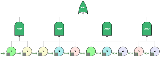
Figure 4: Fault tree for complex "bridge" configuration
Figure 5 presents this configuration in a reliability block diagram, created in BlockSim from the fault tree. This diagram also requires the use of more than one block in the diagram to represent the same component and uses mirror blocks to achieve this.

Figure 5: Reliability block diagram for complex "bridge" configuration
As this article demonstrates, fault tree diagrams and reliability block diagrams can be used to model and analyze similar types of logical configurations required for system reliability and related analyses. The BlockSim software provides a full array of reliability block diagram capabilities as well as an integrated capability for fault tree analysis.
With BlockSim, you can define and analyze fault trees using the major gates and event symbols. You can also expand your traditional fault tree analyses with the maintainability, throughput and other options that are available in BlockSim’s RBDs. You can automatically convert a fault tree to a reliability block diagram and you can also "mix and match" FTDs and RBDs within the same project by, for example, linking a fault tree diagram as a subdiagram to a higher level RBD. More information is available on the web at Blocksim.
This will bring together HBM, Brüel & Kjær, nCode, ReliaSoft, MicroStrain and Discom brands, helping you innovate faster for a cleaner, healthier, and more productive world.

