1. Providing a power signal
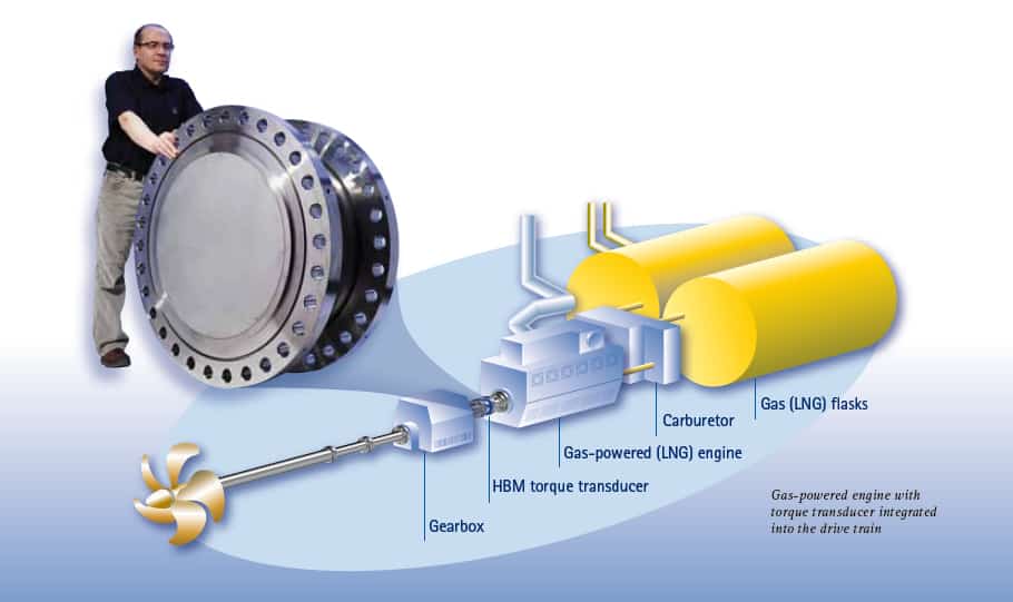
Modern drive concepts with large combustion engines require precise and fast response of the engine's control systems (e.g. for fuel supply) to respond to abruuptly varying loads. Here, it is essential to ensure that sufficient power is supplied at any time and that, at the same time, the engine features low fuel consumption and safe operating parameters. This requires that a power signal is provided which - with vehicles, compressor and pump systems - needs to be generated using special measuring devices. In general, there are three different approaches:
The following article compares direct power measurement with indirect power measurement on and in the drive train respectively (approaches b. and c.) with regard to the uncertainties of measurement that can be achieved.
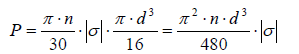
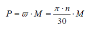 (1)
where M is torque and n rotational speed. Torque is given by
(1)
where M is torque and n rotational speed. Torque is given by
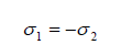 (3)
Since in this case, the center of Mohr's circle is positioned in the origin of its coordinate system, the shear stresses correspond to the absolute value of the principal normal stresses. It follows that
(3)
Since in this case, the center of Mohr's circle is positioned in the origin of its coordinate system, the shear stresses correspond to the absolute value of the principal normal stresses. It follows that
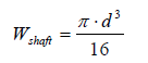 (5)
assuming that the input shaft is a cylindrical solid shaft. Resulting from (1) … (5) power is given by
(5)
assuming that the input shaft is a cylindrical solid shaft. Resulting from (1) … (5) power is given by
 (6)
The normal stress of a torsion shaft is:
(6)
The normal stress of a torsion shaft is:
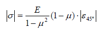 (7)
where E is the modulus of elasticity, μ Poisson's ratio and
(7)
where E is the modulus of elasticity, μ Poisson's ratio and 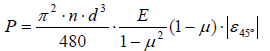 (8)
Example A: Determining strain
(8)
Example A: Determining strain 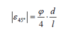 (9)
The single errors to be allowed for result from the tolerances of the input drive's diameter d and length l as well as the measurement error φ, see table 1.
Considering (8) and (9) the power determined by measuring the torsion angle is:
(9)
The single errors to be allowed for result from the tolerances of the input drive's diameter d and length l as well as the measurement error φ, see table 1.
Considering (8) and (9) the power determined by measuring the torsion angle is:
 (10)
(10)
All the parameters to be taken into account for (8) and examples A and B are subject to tolerances. They can be assessed as follows:

Example A requires the strain guage positioning tolerances s as well as the temperature error resulting from lacking or limited thermal compensation to be considered in addition. The values of these tolerances are determined by the quality of the strain gauge installation and will therefore not be take into consideration here.
Without further error analysis, table 1 shows that the total error of the measuring devices described above (approach b) is primarily determines by the tolerance of E and μ. It can thus not be less that 3 %, however, in practice, it is often substantially higher.
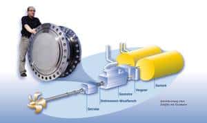 Fig.1: Mounting of a torque flange in a drive train, with an HBM Torque Flange with a nominal (rated) measuring range of 2MNm
According to (1) the power is then given by the directly measured quantities of torque and rotational speed.
The torque flange is calibrated up to its nominal (rated) measuring range or part of it by the supplied and certified accordingly in advance. Depending on the type and size of the measurement flange, the resulting uncertainties of measurement amount to 0.03% and 0.1% of the nominal (rated) or partial measuring range. This uncertainty of measurement is already related to torque and not to an auxiliary quantity, e.g. strain or torsion angle. Due to the integrated thermal compensation, the parameters specified for the measurement flange are valid for a wide temperature range.
Installing, exchanging and recalibration a torque flange is relatively easy. Furthermore, it offers some additional features which - depending on the application - provide significant added value:
Fig.1: Mounting of a torque flange in a drive train, with an HBM Torque Flange with a nominal (rated) measuring range of 2MNm
According to (1) the power is then given by the directly measured quantities of torque and rotational speed.
The torque flange is calibrated up to its nominal (rated) measuring range or part of it by the supplied and certified accordingly in advance. Depending on the type and size of the measurement flange, the resulting uncertainties of measurement amount to 0.03% and 0.1% of the nominal (rated) or partial measuring range. This uncertainty of measurement is already related to torque and not to an auxiliary quantity, e.g. strain or torsion angle. Due to the integrated thermal compensation, the parameters specified for the measurement flange are valid for a wide temperature range.
Installing, exchanging and recalibration a torque flange is relatively easy. Furthermore, it offers some additional features which - depending on the application - provide significant added value:
This will bring together HBM, Brüel & Kjær, nCode, ReliaSoft, and Discom brands, helping you innovate faster for a cleaner, healthier, and more productive world.
This will bring together HBM, Brüel & Kjær, nCode, ReliaSoft, and Discom brands, helping you innovate faster for a cleaner, healthier, and more productive world.
This will bring together HBM, Brüel & Kjær, nCode, ReliaSoft, and Discom brands, helping you innovate faster for a cleaner, healthier, and more productive world.