arrow_back_ios
See All Produtos
See All Conhecimento
See All Soluções
See All Serviços e Suporte
See All Sobre
Main Menu
arrow_back_ios
See All Software
See All Instrumentos
See All Transdutores
See All Teste de vibração
See All Eletroacústica
See All Sistemas de teste acústico de fim de linha
See All Academia
See All Aplicações
See All Indústrias
Main Menu
- Acústica
- Tensão e Corrente
- Deslocamento
- Força
- Células de carga
- Multicomponente
- Pressão
- Deformação
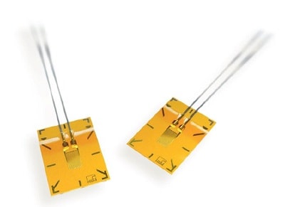
- Strain Gauges
- Temperatura
- Inclinação
- Torque
- Vibração
- Acessórios
- Controladores
- Excitadores de medição
- Excitadores modais
- Amplificadores de potência
- Sistemas Shaker
- Acessórios de Aplicação eletroacústica
- Ouvido artificial
- Boca artificial
- Condução óssea
- Aquisição de dados
- Simulador de cabeça e torso HATS
- Microfone
- Condicionamento de sinal
- Soluções de teste
- Acessórios
- Atuadores
- Motores de combustão
- Durabilidade
- eDrive
- Sistemas móveis
- Sensores de teste de produção
- Caixas de transmissão
- Turbo Charger
arrow_back_ios
See All Simulação e Análise
See All DAQ
See All Drivers API
See All Utilitário
See All Controle de vibração
See All Calibração
See All DAQ
See All Portátil
See All Industrial
See All Analisadores de potência
See All Condicionadores de sinal
See All Acústica
See All Tensão e Corrente
See All Deslocamento
See All Força
See All Células de carga
See All Multicomponente
See All Pressão
See All Deformação
See All Strain Gauges
See All Temperatura
See All Inclinação
See All Torque
See All Vibração
See All Acessórios
See All Controladores
See All Excitadores de medição
See All Excitadores modais
See All Amplificadores de potência
See All Sistemas Shaker
See All Soluções de teste
See All Atuadores
See All Motores de combustão
See All Durabilidade
See All eDrive
See All Sensores de teste de produção
See All Caixas de transmissão
See All Turbo Charger
See All Cursos de formação
See All Acústica
See All Monitorização de activos e processos
See All Energia eléctrica
See All Sensores personalizados
See All NVH
See All Sensores personalizados do OEM
See All Vibração
See All Integridade estrutural
See All Transporte automotivo e terrestre
Main Menu
- Software de controle de vibração
- Aleatório
- Classical Shock
- Replicação da forma de onda temporal
- Sine-on-Random
- Random-On-Random
- Síntese do espectro de resposta ao choque
- Sonômetro
- Medidores de vibração
- Medidores de intensidade sonora
- Dosímetros de ruído
- Software
- Acessórios
- Sistemas multicanais
- Sistema de canal simples
- Piezoelectric Paceline
- Controladores Press Fit
- Amplificadores com display
- Legal for Trade
- Acessórios
- Cartuchos de microfone
- Pré-amplificadores de microfone
- Conjuntos de microfones
- Hidrofones
- Fontes sonoras
- Calibradores
- Microfones especiais
- Acessórios
- Acelerômetros de carga
- Acelerômetros CCLD
- Transdutores de força
- Acelerômetros de referência
- Sondas de tacômetro
- Calibradores
- Acelerômetros ópticos
- Acessórios
- Descontinuado
- Unidade de centralização estática DC
- Fontes de alimentação de campo
- Cabos
- Pinhões
- Suportes de excitação
- Acústica e vibração
- Monitoramento de ativos e processos
- Data Acquisiton
- Teste de energia elétrica
- Ensaios de fadiga e durabilidade
- Ensaio mecânico
- Confiabilidade
- Pesagem
- Ruído do produto
- Teste de ruído de rampa
- Certificação do ruído estático do motor
- Certificação de voo
- Ruído de passagem de veículos
- Electroacoustics
- Identificação da fonte de ruído
- Ruído ambiental
- O que é potência sonora e pressão sonora
- Certificação de ruído
- Teste de Material Acústico
- Teste de produção e garantia de qualidade
- Análise e Diagnóstico de Máquinas
- Monitoramento de integridade estrutural
- Testes de quadros de distribuição
- Alta tensão
- Teste de trem de força
- Teste de bateria
- Teste de máquinas elétricas | Teste de Powertrain | HBM
- Introdução à Medição de Energia Elétrica Durante Transitórios
- Diagrama de circuito equivalente do transformador | HBM
- Teste zero atual
- Conjuntos de sensores personalizados OEM para eBikes
- Conjuntos de sensores personalizados OEM para a indústria agrícola
- OEM Custom Sensor Assemblies para aplicações médicas
- Conjuntos de sensores personalizados para OEM de robótica
- Sensores OEM para a indústria agrícola
- Sensores OEM para aplicações robóticas e de torque
- Sensores médicos OEM
- Teste de Durabilidade - Teste de Fadiga
- Teste de choque e queda
- Teste de embalagens / Vibração de transporte
- Triagem de Estresse Ambiental - ESS
- Qualificação de Satélites Mecânicos
- Zumbido, chiado e chocalho (BSR)
- Teste de bateria de veículos elétricos e híbridos
arrow_back_ios
See All nCode - Análise de Durabilidade e Fadiga
See All ReliaSoft - Análise e gerenciamento de confiabilidade
See All API
See All Ruído do produto
See All Ruído de passagem de veículos
See All Electroacoustics
See All Identificação da fonte de ruído
See All Ruído ambiental
See All O que é potência sonora e pressão sonora
See All Certificação de ruído
See All Teste de produção e garantia de qualidade
See All Análise e Diagnóstico de Máquinas
See All Monitoramento de integridade estrutural
See All Teste de bateria
See All Introdução à Medição de Energia Elétrica Durante Transitórios
See All Diagrama de circuito equivalente do transformador | HBM
See All Sensores OEM para a indústria agrícola
See All Sensores OEM para aplicações robóticas e de torque
See All Dinâmica estrutural
See All Ensaio das propriedades dos materiais
Main Menu
- Testing Of Hands-Free Devices
- Smart Speaker Testing
- Teste de alto-falante
- Teste de aparelhos auditivos
- Teste de auscultadores
- Testes de fones de ouvido e telefones
- Perguntas
- Holografia acústica
- Variação acústica subaquática
- Teste acústico de túnel de vento – Aerospace
- Ensaios em túnel de vento para automóveis
- Beamforming
- Identificação da fonte de ruído
- Identificação de fontes de ruído em tempo real com câmara acústica
- Medidores de intensidade sonora
- Formação de feixe esférico
- PRODUCT NOISE
- Sistema de Medição Acústica
- Acústica de salas e edifícios
- Sistema de medição arquitetónica
- Ruído no local de trabalho
- Poluição sonora urbana
- Potência sonora baseada na intensidade do som
- Pressão sonora - Reverberação Potência sonora baseada na sala
- Certificação de ruído estático do motor
- Ruído Pass-by de Veículos
- Ensaio de ruído de rampa
- Certificação de Voo
- Análise de Pedidos
- Diagnóstico de Máquinas
- Sistemas de monitoramento de integridade e uso (HUMS)
- Teste de turbinas a gás
- Perguntas para análise de máquinas
- Monitoramento de túneis com sensores Fiber Bragg
- Soluções de monitoramento para infraestruturas civis
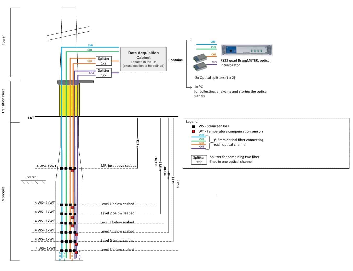
- Soluções de monitoramento para turbinas eólicas
- Soluções de monitorização para a indústria do petróleo e do gás
- Soluções de monitoramento para ferrovias
- Soluções de monitoramento para engenharia civil
- Serviços de monitoramento disponíveis
- Monitorização de fundações utilizando extensómetros