






변형률
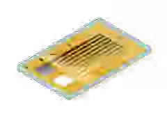
변형률 게이지(변형계)는 더 우수하고 안전한 제품을 만들기 위해 재료의 피로도를 측정하고 시험하는 데 있어 핵심적인 도구입니다. 구조적 내구성 테스트,구조 상태 모니터링, 또는 OEM 트랜스듀서 생산을 위해, HBK의 광학 및 전기 스트레인 게이지를 첫 번째로 선택해야합니다.
Read More

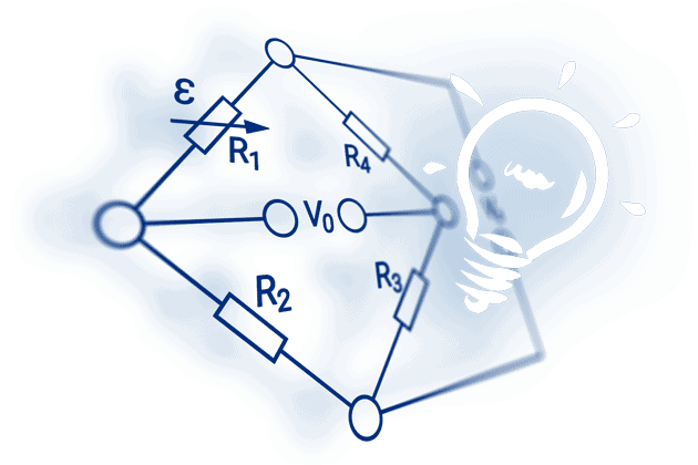
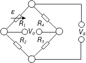
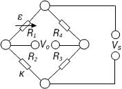
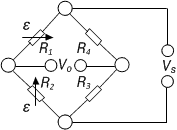
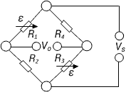
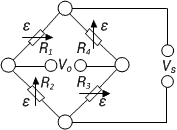
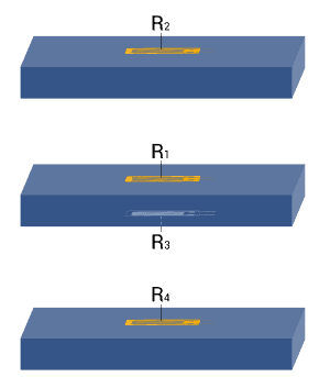
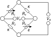
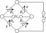
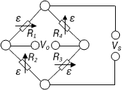
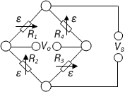
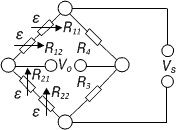
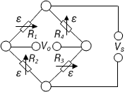
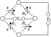
The four arms or branches of the bridge circuit are formed by the resistances R1 to R4. The corner points 2 and 3 of the bridge designate the connections for the bridge excitation voltage Vs. The bridge output voltage V0 , that is the measurement signal, is available on the corner points 1 and 4.
Note: There is no generally accepted rule for the designation of the bridge components and connections. In existing literature, there are all kinds of designations and this is reflected in the bridge equations. Therefore, it is essential that the designations and indices used in the equations are considered along with their positions in the bridge networks in order to avoid misinterpretation.
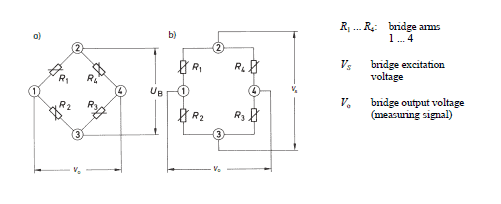
The bridge excitation is usually an applied, stabilized direct, or alternating voltage Vs. If a supply voltage Vs is applied to the bridge supply points 2 and 3, then the supply voltage is divided up in the two halves of the bridge R1, R2 and R4, R3 as a ratio of the corresponding bridge resistances, i.e., each half of the bridge forms a voltage divider.
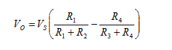
The bridge can be imbalanced, owing to the difference in the voltages from the electrical resistances on R1, R2 and R3, R4. This can be calculated as follows:
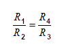

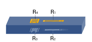
For strain measurements, the resistances R1 and R2 must be equal in the Wheatstone bridge. The same applies to R3 and R4.
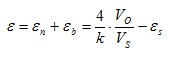
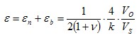
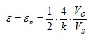
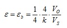
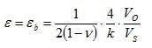
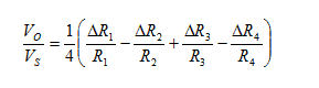
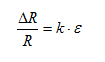
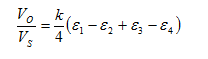
With a few assumptions and simplifications, the following equation can be determined (further explanations are given in the HBM book 'An Introduction to Measurements using Strain Gauges'):

Get a complete overview of the topic of "An Introduction to Measurements using Strain Gauges" - in Karl Hofmann's #1 reference book on stress analysis using strain gauges. In this 250-page, richly illustrated book, Karl Hoffmann describes, in plain language, the fundamentals of strain gauge measurement, ranging from gauge selection through analysis and evaluation of acquired data. Take a look at the book!
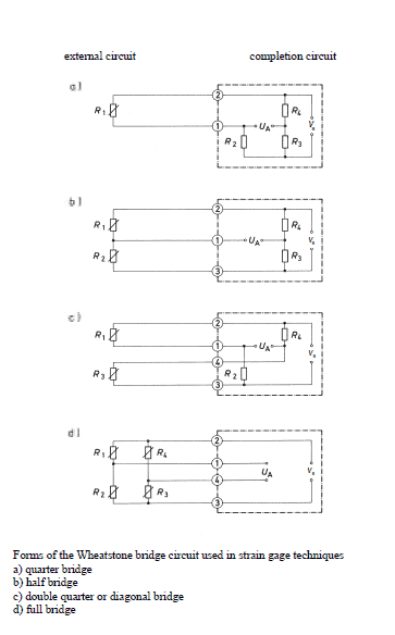
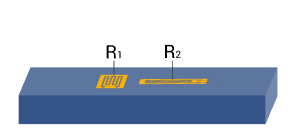
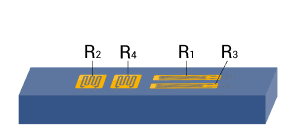
Depending on the measurement task one or more strain gauges are used at the measuring point. Although designations such as full bridge, half bridge, or quarter bridge are used to indicate such arrangements, actually they are not correct. In fact, the circuit used for the measurement is always complete and is either fully or partially formed by the strain gauges and the specimen. It is then completed by fixed resistors, which are incorporated within the instruments.
Transducers generally have to comply with more stringent accuracy requirements than measurements pertaining to experimental tests. Therefore, transducers should always have a full bridge circuit with active strain gauges in all four arms.
Full bridge or half bridge circuits should also be used for stress analysis if different kinds of interferences need to be eliminated. An important condition is that cases of different stresses are clearly distinguished, such as compressive or tensile stress, as well as bending, shear, or torsional forces.
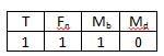
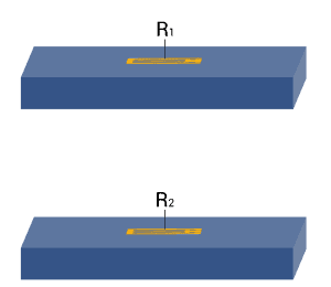
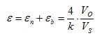
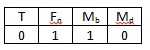
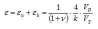
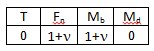
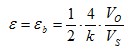
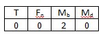
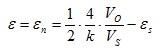
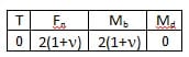
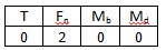
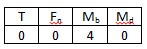
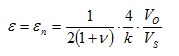
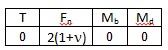
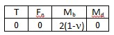
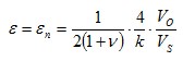
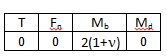
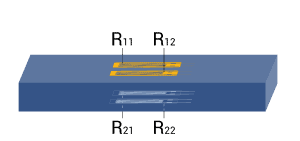
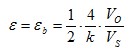
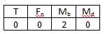
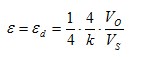
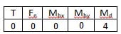
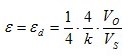
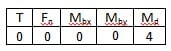
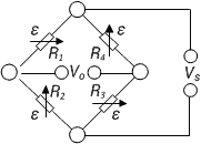
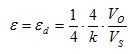
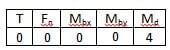
The table below shows the dependence of the geometrical position of the strain gauges, the type of bridge circuit used and the resulting bridge factor B for normal forces, bending moments, torque and temperatures. The small tables given for each example specify the bridge factor B for each type of influencing quantity. The equations are used to calculate the effective strain from the bridge output signal VO/VS.
|
Bridge configuration |
External impacts measured: |
Application |
Description |
Advantages and disadvantages | ||
| 1 |
|
|
| Strain measurement on a tension/ compression bar Strain measurement on a bending beam | Simple quarter bridge
Simple quarter bridge circuit with one active strain gauge | + Easy installation - Normal and bending strain are superimposed - Temperature effects not automatically compensated |
| 2 |
|
|
| Strain measurement on a tension/ compression bar Strain measurement on a bending beam | Quarter bridge with an external dummy strain gauge
Two quarter bridge circuits, one actively measures strain, the other is mounted on a passive component made of the same material, which is not strained | + Temperature effects are well compensated - Normal and bending strain cannot be separated (superimposed bending) |
| 3 |
|
|
| Strain measurement on a tension/ compression bar Strain measurement on a bending beam | Poisson half-bridge
Two active strain gauges connected as a half bridge, one of them positioned at 90° to the other | + Temperature effects are well compensated when material is isotrop |
| 4 |
|
|
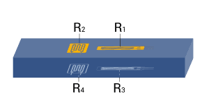
| Strain measurement on a bending beam | Half bridge
Two strain gauges are installed on opposite sides of the structure | + Temperature effects are well compensated + Separation of normal and bending strain (only the bending effect is measured) |
| 5 |
|
|
| Strain measurement on a tension/ compression bar | Diagonal bridge
Two strain gauges are installed on opposite sides of the structure | + Normal strain is measured independently of bending strain (bending is excluded) |
| 6 |
|
|
| Strain measurement on a tension/ compression bar Strain measurement on a bending beam | Full bridge
4 strain gauges are installed on one side of the structure as a full bridge | + Temperature effects are well compensated + High output signal and excellent common mode rejection (CMR) - Normal and bending strain cannot be separated (superimposed bending) |
| 7 |
|
|
| Strain measurement on a tension/ compression bar | Diagonal bridge with dummy gauges
Two active strain gauges, two passive strain gauges | + Normal strain is measured independently of bending strain (bending is excluded) + Temperature effects are well compensated |
| 8 |
|
|
| Strain measurement on a bending beam | Full bridge
Four active strain gauges are connected as a full bridge | + Separation of normal and bending strain (only the bending effect is measured) + High output signal and excellent common mode rejection (CMR) +Temperature effects are well compensated |
| 9 |
|
|
| Strain measurement on a tension/ compression bar | Full bridge
Four active strain gauges, two of them rotated by 90° | + Normal strain is measured independently of bending strain (bending is excluded) + Temperature effects are well compensated + High output signal and excellent common mode rejection (CMR) |
| 10 |
|
|
| Strain measurement on a bending beam | Full bridge
Four active strain gauges, two of them rotated by 90° | + Separation of normal and bending strain (only the bending effect is measured) + Excellent common mode rejection (CMR) + Temperature effects are well compensated |
| 11 |
|
|
| Strain measurement on a bending beam | Full bridge
Four active strain gauges, two of them rotated by 90° | + Separation of normal and bending strain (only the bending effect is measured) + High output signal and excellent common mode rejection (CMR) + Temperature effects are well compensated |
| 12 |
|
|
| Strain measurement on a bending beam | Half bridge
Four active strain gauges connected as a half bridge | + Separation of normal and bending strain (only the bending effect is measured) + Temperature effects are well compensated + High output signal and excellent common mode rejection (CMR) |
| 13 | 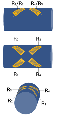 |
|
| Measurement of torsion strain | Full bridge
Four strain gauges are installed, each at an angle of 45° to the main axis as shown | + High output signal and excellent common mode rejection (CMR) + Temperature effects are well compensated |
| 14 | 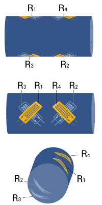 |
|
| Measurement of torsion strain with limited space for installation | Full bridge
Four strain gauges are installed as a full bridge, at an angle of 45° and superimposed (stacked rosettes) | + High output signal and excellent common mode rejection (CMR) + Temperature effects are well compensated |
| 15 | 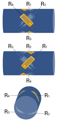 |
|
| Measurement of torsion strain with limited space for installation | Full bridge
Four strain gauges are installed as a full bridge at an angle of 45° and superimposed (stacked rosettes) | + High output signal and excellent common mode rejection (CMR) + Temperature effects are well compensated |
Note: A cylindrical shaft is assumed for torque measurement in example 13, 14, and 15. For reasons related to symmetry, bending in X and Y direction is allowed. The same conditions also apply for the bar with square or rectangular cross sections.
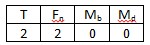
Explanations of the symbols:
| T | Temperature |
| Fn | Normal force |
| Mb | Bending moment |
| Mbx, Mby | Bending moment for X and Y directions |
| Md | Torque |
| εs | Apparent strain |
| εn | Normal strain |
| εb | Bending strain |
| εd | Torsion strain |
| ε | Effective strain at the point of measurement |
| ν | Poisson’s ratio |
 | Active strain gauge |
 | Strain gauge for temperature compensation |
 | Resistor or passive strain gauge |
변형률 게이지(변형계)는 더 우수하고 안전한 제품을 만들기 위해 재료의 피로도를 측정하고 시험하는 데 있어 핵심적인 도구입니다. 구조적 내구성 테스트,구조 상태 모니터링, 또는 OEM 트랜스듀서 생산을 위해, HBK의 광학 및 전기 스트레인 게이지를 첫 번째로 선택해야합니다.

newLight® 광학 변형률 게이지(optical strain gauges)는 넓은 변형률 측정 범위, 내피로성, 간편한 설치, 그리고 습기, 녹, 염분과 같은 가혹한 환경에서도 뛰어난 내구성을 제공합니다.