

Inductive displacement sensors are a reliable measurement tool, which can be found in several industries. With the introduction of amplified digital sensors - containing IO-Link Interface - the sensors become more precise and costs savings are achieved in combination with improved reliability.
There are many reasons for choosing passive sensors, including the temperature limitations of integrated electronics, compatibility with existing designs, cabling requirements, and established in-house expertise. However, many engineers are now choosing IO-Link options with integrated in-line amplifiers across measurement applications such as displacement, force, weight and torque to benefit from lower costs, simplified system architecture and improved reliability and accuracy.
HBK’s displacement sensors are not LVDTs; they are inductive bridge sensors. The bridge principle offers several advantages, including excellent linearity (0.2% or 0.1% depending on the configuration), and a high output signal (80 mV/V), even for very small measurement ranges starting at 2 mm. The measurement principle also provides favourable temperature characteristics, both for TCZero (the effect of temperature on the zero point) and TCSpan (the effect of temperature on sensitivity).
While LVDTs feature three distinct coils (one primary coil and two secondary coils) and operate as transformer-based sensors, HBK’s bridge sensors use either one coil (WA type sensors, ¼-bridge circuit) or two coils (WI type sensors, ½-bridge circuit). Bridge completion is performed using passive electrical resistors, allowing any bridge amplifier with a suitable carrier with a suitable frequency of 4.8 kHz to 5 kHz to be used.
A moveable core changes the inductance of the coils. When the circuit is supplied with an appropriate voltage, movement of the core changes the inductance, which in turn changes the voltage drop across the coil. Using the Wheatstone bridge principle, this is converted into a measurable output voltage that is linearly related to displacement.
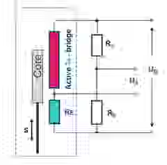
Inductive ¼-bridge, measurement principle of our WA sensors
Output: 80 mV/V, suitable for carrier frequency voltage supply of 4.8 – 5 kHz
HBK’s passive WA displacement sensors provide the longest cable length of more than 100 m as they use a ‘6 wire connection’ which compensates the voltage drop of longer cables - also the changes of resistance that occur due to temperature changes. WA sensors are available as a plug version to make them easier to accommodate a longer cable. If you choose to have a ‘current out’ or ‘voltage output’ signal, the cable length is limited to 30 m.
For IO-Link options with integrated amplifiers, cabling requirements are reduced, and the maximum cable length is 20m from the sensor output to the IO-Link master.
Displacement sensors with an inline amplifier offer higher accuracy through digital compensation of linearisation errors.
For passive sensors, we use a special mechanical procedure to adapt the moveable core to the coil. This guarantees a low linearity error and a suitable output signal.
For sensors with an inline amplifier, this working step is a digital process - one moveable core is always adapted to one coil system. If a moveable core is damaged and needs replacing, our repair team can help. We will ensure that the new core fits to the existing coil system or, if an inline amplifier is used, to the existing amplifier.
With all displacement sensors, the freedom of movement of the moveable core is larger than the measurement range. So it’s important to define the beginning of the measurement range as a first step. The mechanical adjustment depends on the type of sensors that you are using. You can find the starting point for all passive sensors as follows:
- With WA-L and WA-T the measurement range starts at an output signal of 0 mV/V
- The WI Sensors come with a half bridge configuration so that the measurement range starts at – 40 mV/V
Hint: Please check if there are zero-point values stored in your amplifier system before adjusting your sensor in its start position. Your zero value should be 0 mV/V.
- For current or ‘voltage out’ options, the measurement range starts at 0 V or 4 mA respectively
- Digital sensors with an IO-Link interface enable ‘plug and measure’ simplicity – they start to measure and send correct readings to the master as soon as they are connected. The measurement range starts at 0 mm for all types. With digital sensors the positioning is much easier due to a feature in the process data that indicates if the moveable coil is placed within the measurement range - please refer to the manual or the quick start guides.

This will bring together HBM, Brüel & Kjær, nCode, ReliaSoft, MicroStrain and Discom brands, helping you innovate faster for a cleaner, healthier, and more productive world.

